In this article, you will learn the PLC programming example on timers function block using switch and lamps.
Note: The PLC example logic presented is for educational resource for engineering students and technicians to learn the basics.
Problem Statement
Design a PLC ladder logic for the following application.
We are using one toggle switch to control two lamps.
When Switch 1 is ON, then
Watch the below video to master the PLC programming for beginners.
Digital Inputs:
The list of digital inputs shown below.
Switch 1: I0.0
Digital Outputs:
The list of digital outputs shown below.
Lamp 1: Q0.0
Lamp 2: Q0.1
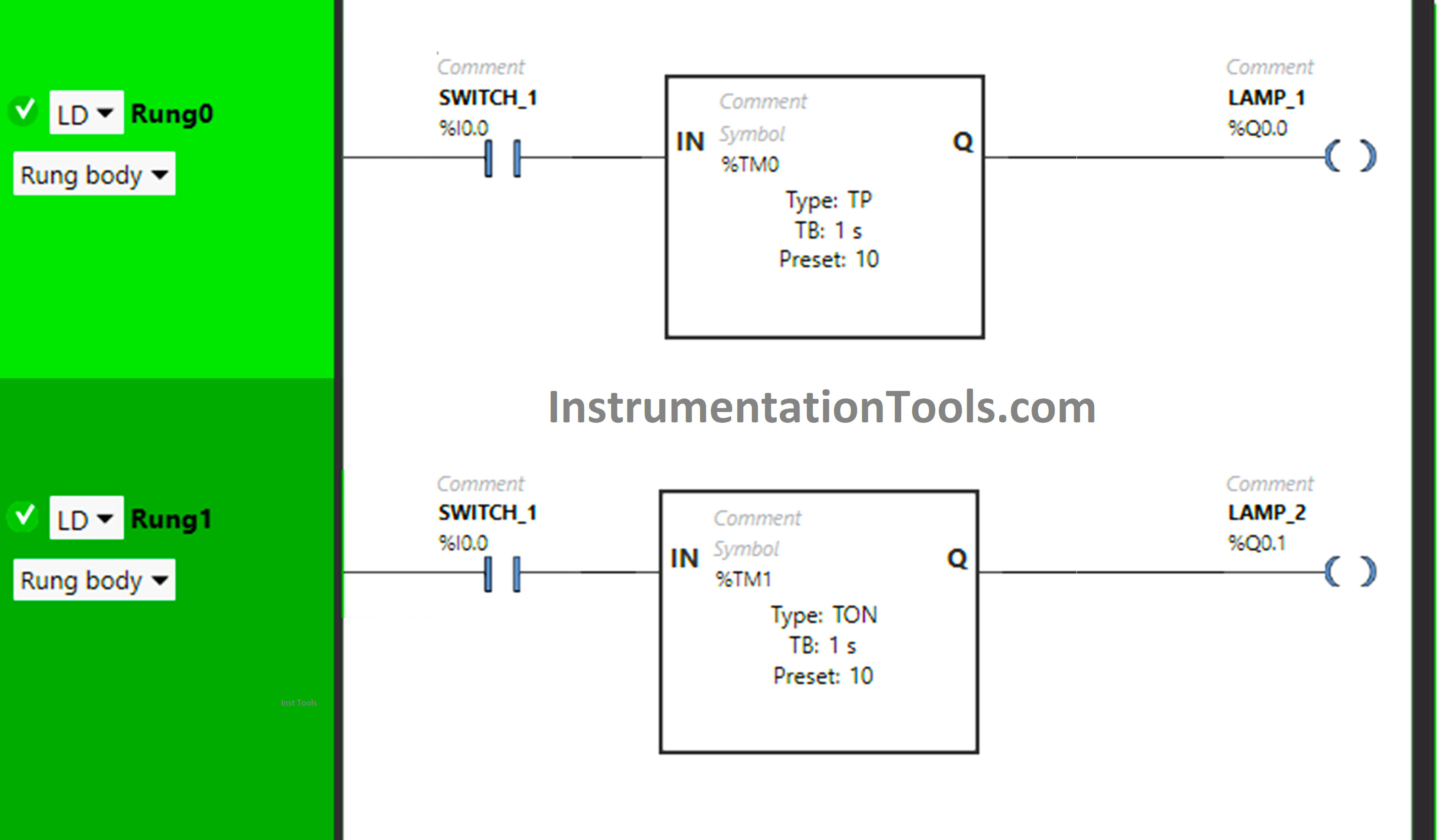
Here we used Normally Open Contact for Switch 1 (I0.0).
Timer Function Block Type TP is used for Lamp 1 and Time Function Block Type TON is used for Lamp 2.
In Rung 0:
1) Normally Open Contact is used for Switch 1 to Turn ON Lamp 1.
2) Timer Function Block type TP is used to Turn OFF Lamp 1 after Set time.
In Rung 1:
1) Normally Open Contact is used for Switch 1 to Turn ON Lamp 2.
2) Timer Function Block type TON is used to delay the time of Lamp 2 to Turn ON.
When Switch 1 is ON, the signal will flow through Switch 1 as Normally Open Contact is used for Switch 1 and Lamp 1 will Turn ON for 10 seconds because Timer Function Block type TP is used for Lamp1 and time is set for 10 sec.
After 10 seconds, Lamp 2 will Turn ON in Rung1 as Timer Function Block type TON is used for Lamp 2 to delay the turning ON and time is set for 10 sec.
Here we show the PLC logic simulation results.
When Switch 1 is ON
When Switch 1 is turned ON, Lamp 1 will Turn ON for 10s in Rung 0 as Timer Function Block Type TP is used for Lamp 1.
After 10 seconds, Lamp 1 will Turn OFF and Lamp 2 will Turn ON in Rung 1 because Timer Function Block Type TON is used for Lamp 2 which will delay the time of Lamp 2 to Turn ON for Set time.
If you liked this article, please subscribe to our YouTube Channel for PLC and SCADA video tutorials.
You can also follow us on Facebook and Twitter to receive daily updates.
Read Next:
This article is about controlling the double-acting pneumatic cylinder movement control with a timer circuit.
In this article, we will review the main responsibility scopes of the instrumentation and electrical…
Learn the daily alarm PLC program using real-time clock instruction as per the required timings…
A Real-Time Clock accurately tracks time from seconds to years and stores the data in…
Omron PLC logic for sorting the number of products and counting the number of products…
Learn the water fountain control logic using the PLC timers programming to control the high…


