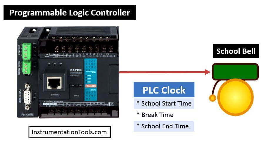
In a school, bell is activated by the PLC system. The bell will ring automatically at a fixed timing for 5 seconds interval. Write PLC program for this system using ladder logic programming.
The required bell timings are at school start time, break time and school end time.
Automatic Bell System
Solution
For this automatic system we will use PLC programming. Here we read PLC time in the program and compare it.
For example in school we need to ring bell at three different time (School begin, breaks and end of the school.).
So compare this three different time using comparators. Also we will generate three different conditions for the bell output.
List of Inputs/Outputs
List of Outputs
- Q0.0 :- School bell
M memory
- M0.0 :- School begin bell ringing command
- M0.1 :- Break time bell ringing
- M0.2 :- School end bell ringing command
- Internal tag 1 :- Actual time
- Internal tag 2 :- School begin time
- Internal tag 3 :- Break time
- Internal tag 4:- School end time
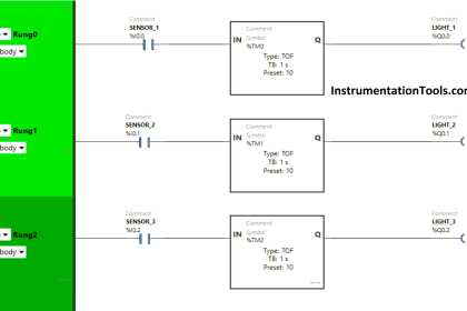
Ladder diagram for Automatic School Bell System


Logic Description
Network 1 :-
Here School begin time is compared with actual time of the PLC clock. Bell condition will remain ON for 10s (seconds) and after 10s it will be OFF automatically.
Network 2 :-
Here School break time is compared with actual time of the PLC clock. Bell condition will remain ON for 5s and after 10s it will be OFF automatically.
Network 3 :-
Here School end time is compared with actual time of the PLC clock. Bell condition will remain ON for 10s and after 10s it will be OFF automatically.
Network 4 :-
Any condition out of three is triggered bell output will be ON.
Note :- Above application may be different from actual application. This example is only for explanation purpose only. We can implement this logic in other PLC also. This is the simple School bell control using PLC, we can use this concept in other examples also.
All parameters and graphical representations considered in this example are for explanation purpose only, parameters or representation may be different in actual applications. Also all interlocks are not considered in the application.
Author : Bhavesh
If you liked this article, then please subscribe to our YouTube Channel for PLC and SCADA video tutorials.
You can also follow us on Facebook and Twitter to receive daily updates.
Read Next: