Inst ToolsInst ToolsInst Tools
  • Courses
  • Automation
    • PLC
    • Control System
    • Safety System
    • Communication
    • Fire & Gas System
  • Instrumentation
    • Design
    • Pressure
    • Temperature
    • Flow
    • Level
    • Vibration
    • Analyzer
    • Control Valve
    • Switch
    • Calibration
    • Erection & Commissioning
  • Interview
    • Instrumentation
    • Electrical
    • Electronics
    • Practical
  • Q&A
    • Instrumentation
    • Control System
    • Electrical
    • Electronics
    • Analog Electronics
    • Digital Electronics
    • Power Electronics
    • Microprocessor
  • Request
Search
  • Books
  • Software
  • Projects
  • Process
  • Tools
  • Basics
  • Formula
  • Power Plant
  • Root Cause Analysis
  • Electrical Basics
  • Animation
  • Standards
  • 4-20 mA Course
  • Siemens PLC Course
Reading: P&ID Guidelines for Storage Tanks
Share
Font ResizerAa
Inst ToolsInst Tools
Font ResizerAa
  • Courses
  • Design
  • PLC
  • Interview
  • Control System
Search
  • Courses
  • Automation
    • PLC
    • Control System
    • Safety System
    • Communication
    • Fire & Gas System
  • Instrumentation
    • Design
    • Pressure
    • Temperature
    • Flow
    • Level
    • Vibration
    • Analyzer
    • Control Valve
    • Switch
    • Calibration
    • Erection & Commissioning
  • Interview
    • Instrumentation
    • Electrical
    • Electronics
    • Practical
  • Q&A
    • Instrumentation
    • Control System
    • Electrical
    • Electronics
    • Analog Electronics
    • Digital Electronics
    • Power Electronics
    • Microprocessor
  • Request
Follow US
All rights reserved. Reproduction in whole or in part without written permission is prohibited.
Inst Tools > Blog > Erection & Commissioning > P&ID Guidelines for Storage Tanks

P&ID Guidelines for Storage Tanks

Last updated: September 29, 2016 3:01 pm
Editorial Staff
Erection & Commissioning
No Comments
Share
3 Min Read
SHARE

Storage tanks of various kinds are used to store process fluids of various types, under different process conditions. But the basic arrangement remains roughly the same for different types of storage tanks.

P&ID Guidelines for Storage Tanks

  1. Proper tank symbol should be selected first of all, as shown in the presented drawing. This should be selected from the list of equipment symbols on the legend sheets of a particular project.
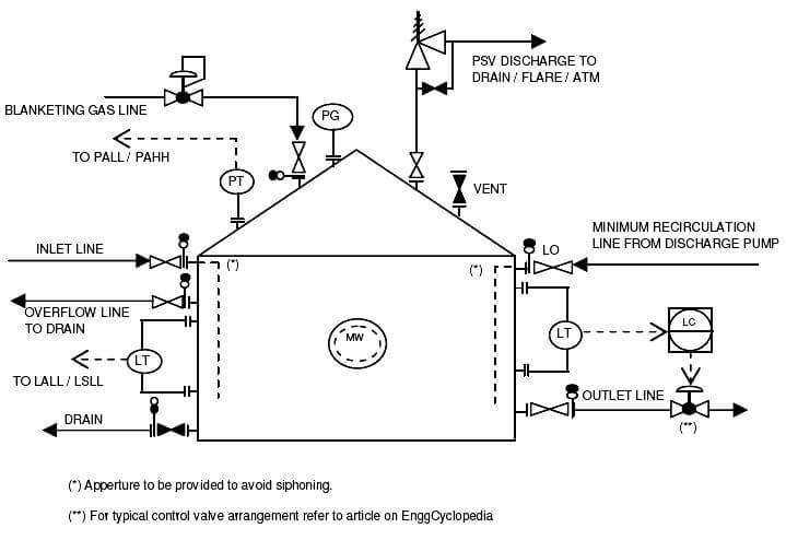
  2. Tank internals should then be indicated as per proper symbols on the legend sheets. These internals can be inlet pipe, vortex breaker on the outlet lines etc.
  3. All the nozzles on the storage tank should then be correctly represented with size and flanges. This includes inlet and outlet nozzles, overflow line, minimum recirculation line, blanketing gas line, drains, vents, PSV connection and instrument nozzles, as shown in the sample drawing presented here. Normally for large enough tanks a manway has to be provided as indicated in the sample drawing for maintenance access.
  4. Inlet and outlet lines are the next to be drawn up. Line number, material class, size etc. is to be correctly assigned to each of the lines.
  5. Typical instrumentation on the tank would be level gauges and transmitters plus pressure gauge and transmitters. For tank under continuous operation a level control valve has to be provided as indicated in the sample drawing. For tank with blanketing gas a self regulating pressure valve has to be provided on the blanketing gas inlet line. Normally alarms / trips are provided for High High Pressure, High High Level, Low Low Pressure and Low Low Level.
  6. Isolation valves, spectacle blinds, spacers etc. to be used for maintenance should be drawn up next on the inlet / outlet lines. The spectacle blinds, spacers etc. can be connected right next to the isolation valves and equipment nozzles, as indicated in the sample drawing presented here.
  7. Drains should be provided on the tank bottom and on the bottom outlet lines for complete draining of  the tank and associated piping for maintenance purpose.
  8. Vent has to be provided on top of the tank for complete venting of the tank for maintenance purpose. In some cases the tank may be open to atmosphere through vent during normal operation. In such cases a bird screen has to be provided on the vent line.
  9. For purging the tank with nitrogen or steam, a utility connection can be provided directly on the tank.
  10. All the guidelines given here are very general and may be modified as per specific requirements of any particular project.
Don't Miss Our Updates
Be the first to get exclusive content straight to your email.
We promise not to spam you. You can unsubscribe at any time.
Invalid email address
You've successfully subscribed !

Continue Reading

Selection Guidelines for Cable Glands
DP Level Measurement Problems
What is FAT and SAT? Difference between them
Important Factors Consider during Piping Design
How to Solve Cable Tray Sagging ?
Pressure Transmitter Vent fittings
Share This Article
Facebook Whatsapp Whatsapp LinkedIn Copy Link
Share
Leave a Comment

Leave a Reply Cancel reply

Your email address will not be published. Required fields are marked *

Stay Connected

128.3kFollowersLike
69.1kFollowersFollow
210kSubscribersSubscribe
38kFollowersFollow

Categories

Explore More

Installation & Commissioning Tips for HART Devices
What is Double Block and Bleed Valves?
How to Install Thermowell on an Elbow?
Good and Bad Wiring Practices
What is Instrument Hook Up Diagram ?
Control Valves Pre-Commissioning Checklist
Tips for Reducing the Noise Signals
How to Install Ultrasonic Level Transmitters

Keep Learning

Wrong Orifice Installation

How Not to Install an Instrument and Wrong Practices

Direct Mounting of Diaphragm Seals Level Transmitter

What are the Mounting Techniques of Diaphragm Seals?

Thermocouple Temperature Measurements Errors

Thermocouple Temperature Measurement Errors

cable-trays-glossary

Cable Trays Glossary

pid-guidelines-for-pig-receivers

P&ID Guidelines for Pig Receivers

Pressure Transmitter Installation

Field Instruments Mounting brackets

P&ID Guidelines for Pumps

P&ID Guidelines for Pumps

P&ID Guidelines for Pumps Heat Exchangers

P&ID Guidelines for Pumps Heat Exchangers

Learn More

OTDR testing

OTDR Testing

Function Module in Siemens PLC

What is Function Module in Siemens PLC?

Instrument Skid

What is an Instrument Skid? – Example of Metering Skid

Compounded DC Generator

Parallel AC Generators

Single-Phase Induction Motors Multiple Choice Questions (MCQ)

125+ Single-Phase Induction Motors Multiple Choice Questions (MCQ)

Transformer Efficiency

Transformer Efficiency

Thermocouple Questions

Thermocouple Terminal block Questions

Turbine Flow Meters Working Animation

Turbine Flow Meters Animation

Menu

  • About
  • Privacy Policy
  • Copyright

Quick Links

  • Learn PLC
  • Helping Hand
  • Part Time Job

YouTube Subscribe

Follow US
All rights reserved. Reproduction in whole or in part without written permission is prohibited.
Welcome Back!

Sign in to your account

Username or Email Address
Password

Lost your password?