Inst ToolsInst ToolsInst Tools
  • Courses
  • Automation
    • PLC
    • Control System
    • Safety System
    • Communication
    • Fire & Gas System
  • Instrumentation
    • Design
    • Pressure
    • Temperature
    • Flow
    • Level
    • Vibration
    • Analyzer
    • Control Valve
    • Switch
    • Calibration
    • Erection & Commissioning
  • Interview
    • Instrumentation
    • Electrical
    • Electronics
    • Practical
  • Q&A
    • Instrumentation
    • Control System
    • Electrical
    • Electronics
    • Analog Electronics
    • Digital Electronics
    • Power Electronics
    • Microprocessor
  • Request
Search
  • Books
  • Software
  • Projects
  • Process
  • Tools
  • Basics
  • Formula
  • Power Plant
  • Root Cause Analysis
  • Electrical Basics
  • Animation
  • Standards
  • 4-20 mA Course
  • Siemens PLC Course
Reading: pi filter Operation
Share
Font ResizerAa
Inst ToolsInst Tools
Font ResizerAa
  • Courses
  • Design
  • PLC
  • Interview
  • Control System
Search
  • Courses
  • Automation
    • PLC
    • Control System
    • Safety System
    • Communication
    • Fire & Gas System
  • Instrumentation
    • Design
    • Pressure
    • Temperature
    • Flow
    • Level
    • Vibration
    • Analyzer
    • Control Valve
    • Switch
    • Calibration
    • Erection & Commissioning
  • Interview
    • Instrumentation
    • Electrical
    • Electronics
    • Practical
  • Q&A
    • Instrumentation
    • Control System
    • Electrical
    • Electronics
    • Analog Electronics
    • Digital Electronics
    • Power Electronics
    • Microprocessor
  • Request
Follow US
All rights reserved. Reproduction in whole or in part without written permission is prohibited.
Inst Tools > Blog > Electronic Devices & Circuits > pi filter Operation

pi filter Operation

Last updated: September 27, 2016 3:43 pm
Editorial Staff
Electronic Devices & Circuits
No Comments
Share
2 Min Read
SHARE

The below Fig shows a typical capacitor input filter or π- filter. It consists of a filter capacitor C1 connected across the rectifier output, a choke L in series and another filter capacitor C2  connected across the load. Only one filter section is shown but several identical sections are often used to improve the smoothing action

pi filter Operation

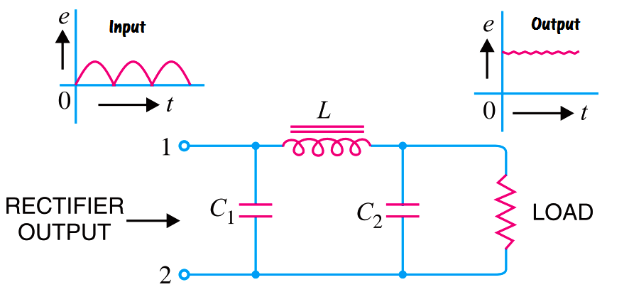
The pulsating output from the rectifier is applied across the input terminals (i.e. terminals 1 and 2) of the filter. The filtering action of the three components viz C1, L and C2  of this filter is described below

(a)  The filter capacitor C1 offers low reactance to a.c. component of rectifier output while it offers infinite reactance to the d.c. component. Therefore, capacitor C1 bypasses an appreciable amount of a.c. component while the d.c. component continues its journey to the choke L.

(b)  The choke L offers high reactance to the a.c. component but it offers almost zero reactance to the d.c. component. Therefore, it allows the d.c. component to flow through it, while the unbypassed a.c. component is blocked.

(c)  The filter capacitor C2 bypasses the a.c. component which the choke has failed to block. Therefore, only d.c. component appears across the load and that is what we desire.

pi filter

Capacitor input filters can provide extremely pure DC supplies, but have fallen out of favour because inductors tend to be unavoidably heavy, which has led to the often-preferred choice of voltage regulators instead.

Advantages of pi filters:

  • More output voltage
  • Ripple-free output

Disadvantages of pi filters:

  • Large size
  • Heavy
  • High cost
Don't Miss Our Updates
Be the first to get exclusive content straight to your email.
We promise not to spam you. You can unsubscribe at any time.
Invalid email address
You've successfully subscribed !

Continue Reading

Transistor as a Switch Working Principle
Forward Bias & Reverse Bias Diode Working Animation
Insulators, Conductors and Semiconductors
Transistor Collector Feedback Bias
Characteristics of Photo diode
Permanent Magnet Moving Coil Instruments (PMMC)
Share This Article
Facebook Whatsapp Whatsapp LinkedIn Copy Link
Share
Leave a Comment

Leave a Reply Cancel reply

Your email address will not be published. Required fields are marked *

Stay Connected

128.3kFollowersLike
69.1kFollowersFollow
210kSubscribersSubscribe
38kFollowersFollow

Categories

Explore More

Ideal Diode Characteristics
Transistor Collector Characteristic Curves
Optoisolator Working Principle
Transistors Questions & Answers
Resistors Principle & Applications
Basics of Amplifiers Interview Questions
Peak Inverse Voltage of Center Tap Rectifier
Schottky Diode Working Principle

Keep Learning

transistor-emitter-bias

Transistor Emitter Bias

Types of Resistors

Types of Resistors

Fluorescent Screen of CRT

CRT Fluorescent Screen

Transistor Stabilisation

Transistor Stabilisation

Classification of Bridge Circuits

Classification of Bridge Circuits

transistor-base-bias

Transistor Base Bias

diode-clamper-circuit

Diode Clampers Principle

Combining Independent Voltage Sources in Series

Combining Independent Voltage Sources in Series

Learn More

Strain gage load cells

Load Cell Healthiness Checks

Scaling in PLC

PLC Ladder Logic for Sensor Scaling with Offset

Instrumentation Engineer in Process Plant Project

Instrumentation Engineer in Process Plant Project

Instrument Process Datasheet

Why is an Instrument Process Datasheet Required?

Orifice Flow Meter With DP Transmitter

What is an Orifice Meter?

Inspection of Control Valves

Inspection and Test Requirement of Control Valves

Electrical Machines Objective Questions

Electrical Machines MCQ Series 5

Pneumatic Actuators Types Animation

Types of Pneumatic Actuators Animation

Menu

  • About
  • Privacy Policy
  • Copyright

Quick Links

  • Learn PLC
  • Helping Hand
  • Part Time Job

YouTube Subscribe

Follow US
All rights reserved. Reproduction in whole or in part without written permission is prohibited.
Welcome Back!

Sign in to your account

Username or Email Address
Password

Lost your password?