Inst ToolsInst ToolsInst Tools
  • Courses
  • Automation
    • PLC
    • Control System
    • Safety System
    • Communication
    • Fire & Gas System
  • Instrumentation
    • Design
    • Pressure
    • Temperature
    • Flow
    • Level
    • Vibration
    • Analyzer
    • Control Valve
    • Switch
    • Calibration
    • Erection & Commissioning
  • Interview
    • Instrumentation
    • Electrical
    • Electronics
    • Practical
  • Q&A
    • Instrumentation
    • Control System
    • Electrical
    • Electronics
    • Analog Electronics
    • Digital Electronics
    • Power Electronics
    • Microprocessor
  • Request
Search
  • Books
  • Software
  • Projects
  • Process
  • Tools
  • Basics
  • Formula
  • Power Plant
  • Root Cause Analysis
  • Electrical Basics
  • Animation
  • Standards
  • 4-20 mA Course
  • Siemens PLC Course
Reading: Overview of HIPPS System
Share
Notification Show More
Font ResizerAa
Inst ToolsInst Tools
Font ResizerAa
  • Courses
  • Design
  • PLC
  • Interview
  • Control System
Search
  • Courses
  • Automation
    • PLC
    • Control System
    • Safety System
    • Communication
    • Fire & Gas System
  • Instrumentation
    • Design
    • Pressure
    • Temperature
    • Flow
    • Level
    • Vibration
    • Analyzer
    • Control Valve
    • Switch
    • Calibration
    • Erection & Commissioning
  • Interview
    • Instrumentation
    • Electrical
    • Electronics
    • Practical
  • Q&A
    • Instrumentation
    • Control System
    • Electrical
    • Electronics
    • Analog Electronics
    • Digital Electronics
    • Power Electronics
    • Microprocessor
  • Request
Follow US
All rights reserved. Reproduction in whole or in part without written permission is prohibited.
Inst Tools > Blog > Control Systems > Overview of HIPPS System

Overview of HIPPS System

Last updated: March 25, 2019 11:03 am
Editorial Staff
Control Systems
4 Comments
Share
7 Min Read
SHARE

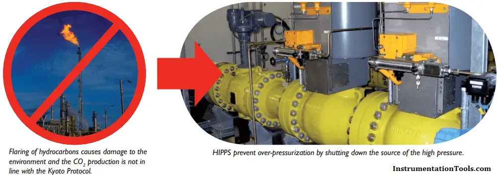
HIPPS is an abbreviation of “High Integrity Pressure Protection System”. HIPPS systems are applied to prevent over-pressurisation of a plant by shutting-off the source of the high pressure.

In traditional systems over-pressure is dealt with through relief systems. Relief systems have obvious disadvantages such as release of (flammable and toxic) process fluids in the environment and often a large footprint of the installation. With the increasing environmental awareness relief systems are no longer an acceptable solution.

HIPPS is applied to prevent over-pressurisation of a plant or pipeline by shutting off the source of the high pressure.

HIPPS provides a technically sound and economically attractive solution to protect equipment in cases where:

  • High-pressures and / or fl ow rates are processed
  • The environment is to be protected.
  • The economic viability of a development needs improvement
  • The risk profile of the plant must be reduced

HIPPS is an instrumented safety system that is designed and built in accordance with the IEC 61508 and IEC 61511 standards.

What is HIPPS?

The international standards IEC 61508 and 61511 refer to safety functions and Safety Instrumented Systems (SIS) when discussing a device to protect equipment, personnel and environment.

Older standards use terms like safety shut-down systems, emergency shut-down systems or last layers of defence. A system that closes the source of over-pressure within 2 seconds with at least the same reliability as a safety relief valve is usually called a HIPPS.

HIPPS System

A High Integrity Pressure Protection System is a complete functional loop consisting of:

  • The sensors, (or initiators) that detect the high pressure
  •  The logic solver, which processes the input from the sensors to an output to the final element
  • The final elements, that actually perform the corrective actions in the field by bringing the process to a safe state. The final element consists of a valve, actuator and possibly solenoids.
Traditional systems
In traditional systems over-pressure is dealt with through relief systems. Relief systems have obvious disadvantages such as release of (flammable and toxic) process fluids in the environment and often result in a large footprint of the installation. With increasing environmental awareness relief systems are no longer an acceptable solution. A relief system aims at removing any excess inflow, where as a HIPPS aims at stopping the inflow of excess fluids and thus avoiding over-pressure.High Integrity Pressure Protection System HIPPS
Advantages of HIPPS
HIPPS provides a technically sound and economically attractive solutions to protect equipment in cases where:
  • High pressures and / or flow rates are processed
  • The environment is to be protected
  • The economic viability of a development needs improvement
  • The risk profile of the plant must be reduced

 Overview of  HIPPS

 HIPPS is an instrumented safety system that is designed and built in accordance with the IEC 61508 and IEC 61511 standards. These international  standards refer to safety functions (SF) and Safety Instrumented Systems (SIS) when discussing a solution to protect equipment, personnel and environment.
A system that closes the source of over-pressure within 2 seconds, with at least the same reliability as a safety relief valve, is usually identified as a HIPPS.
A HIPPS is a complete functional loop consisting of:
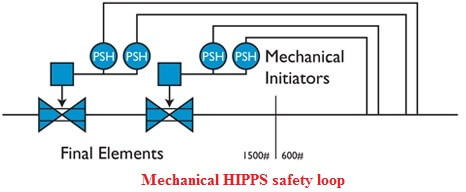
  • The initiators that detect the high pressure. These initiators may be electronic or mechanical.
  • For electronic HIPPS, a logic solver, which processes the input from the initiators to an output to the final element.
  • The final elements, that actually perform the corrective action in the field by bringing the process to a safe state. The final element consists of a valve and actuator and possibly solenoids or mechanical initiators.

Two types of HIPPS

 Based on experience and expertise offers two types of HIPPS
1.     Integral mechanical HIPPS, since 1974
2.     Full electronic HIPPS, since 2000

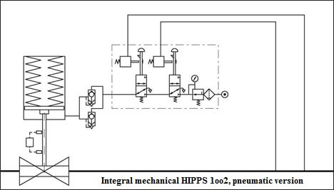
1. Integral mechanical HIPPS – using mechanical initiators

In 1974 the German DVGW certified the final element including mechanical initiators in accordance with EN 14382 (former DIN 3381). Since that date has field experience with safety shut-off valves (with actuator and initiator) closing within 2 seconds.
Mechanical HIPPS safety loop
Main features of integral mechanical HIPPS:
  • Integrated safety loop to IEC 61508 / EN 12186
  • Safe and simple
  • Option not requiring external energy (stand-alone HIPPS)
  • No wiring required
  • Set point accuracy < 1%
  • System to SIL 3 or 4
  • Third party validated failure data
 Mechanical HIPPS System
2. Full electronic HIPPS – with electronic pressure transmitters
When designing a HIPPS always treats a HIPPS (and other SIS) as a complete certified functional loop and not on separate component level. Safety wise the HIPPS loop is designed in accordance with IEC 61508 and 61511. On the specification side of the final element the design is in accordance with EN 14382 (DIN 3381).
The misunderstanding that ‘system’ stands for controller and that a SIS can be designed on component level, is the cause of the biggest problem in the implementation of HIPPS. The under specification of mechanical components and the acceptance of component Safety Integrity Level (SIL) certification, instead of verification of the complete loop SIL is still a pitfall.
 Electronic HIPPS safety loop
Main features of full electronic HIPPS:
  • Integrated safety loop to IEC 61508 and 61511
  • No limit on distance between transmitters and final element
  • Communication with Plant Safety System
  • Possibility of integrated monitoring
  • Hard-wired solid-state logic solver
  • High integrity manifold block for safer operation
  • System to SIL 3 or 4

Electronic HIPPS System

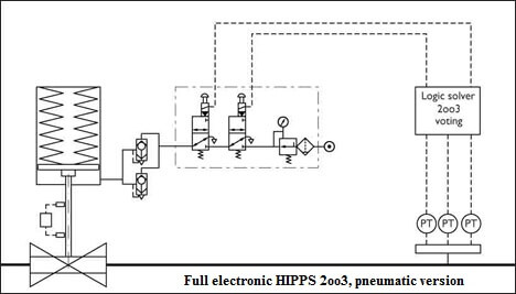
HIPPS System: 1002 Electronic HIPPS system

1oo2-electronic-HIPPS

Also Read: Safety System Interview Questions

Don't Miss Our Updates
Be the first to get exclusive content straight to your email.
We promise not to spam you. You can unsubscribe at any time.
Invalid email address
You've successfully subscribed !

Continue Reading

Most Asked Questions on SCADA with Answers
Loop Calibrator to Simulate a 4-20 mA Signal
Network Cabling
Comparison of Control Loops – Open, Closed, Cascade, Feedforward, Ratio
Importance of Grounding Electronic Equipment
DCS Program to Maintain Draft in Furnace
Share This Article
Facebook Whatsapp Whatsapp LinkedIn Copy Link
Share
4 Comments
  • Aditya says:
    August 18, 2023 at 6:21 am

    There is no standard that HIPPS shall be closed the Valves within 2 seconds. It is up to client to calculate the Closing time considering many effects to pipeline when Overpressure happen and suddenly pipeline will be closed within 2 seconds.

    Reply
  • Akhildas PS says:
    November 29, 2023 at 2:24 pm

    Please make a separate article for High Integrity Manifold Block (ASTAVA) and Planar4 – Solid state logic solver

    Reply
  • Luis Black says:
    February 20, 2025 at 2:49 am

    Hello.
    Can a hipps system have two different set of initiators?

    Reply
    • john says:
      February 21, 2025 at 12:32 pm

      Yes, a HIPPS can have two different sets of initiators to enhance redundancy, reliability, and meet SIL requirements. This setup reduces false trips and ensures safety through voting logic like 2oo3 or 1oo2 configurations.

      Reply

Leave a Reply Cancel reply

Your email address will not be published. Required fields are marked *

Stay Connected

128.3kFollowersLike
69.1kFollowersFollow
210kSubscribersSubscribe
38kFollowersFollow

Categories

Explore More

Fault in the Temperature Loop
Anti-static Wrist Straps in Industrial Automation
Loop-powered 4-20 mA Transmitter Circuit Voltage drop
Siemens PLC Course for Beginners: Problems and Solutions
Industrial Networking and Wireless Interview Questions
Why Baud Rate is Important in Modbus Network?
Manufacturing Execution System (MES) in Industrial Automation
What is Open Telemetry? – Principles and Benefits

Keep Learning

Field Instrument package

Package System Architecture – Control & Instrumentation

30 Concerns for Control System Philosophy (Industrial Automation)

30 Concerns for Process Control Systems Philosophy

Nuisance Alarms

What is Alarm Shelving? – Nuisance Alarms, Types, Suppression

What is a Feedback Control System

What is a Feedback Control System? Types & Advantages

Ziegler-Nichols closed-loop Tuning - 1

Heuristic PID Tuning Method

Control Panel

What is a Control Panel and its types?

Hot Well Level Control System in Condensing Turbine

Hot Well Level Control System in Condensing Turbine

Four Wire HART Transmitters

4-wire Passive versus Active Transmitters

Learn More

Control Valve in Nutshell - Valve Design and Selection Factors

Control Valve in Nutshell – Valve Design and Selection Factors

Battery Hazard

Battery Hazards

Distributed Control System Architecture for Profibus Field Instruments

H1 FF Physical layer

Robotic Automation

Robotic Process Automation (RPA) in AI – Market Growth & Business Benefits

DCS ESD Logic Overview Graphic Display

Automation System Process Functionalities

Generator Action in a Motor

Generator Action in a Motor

4-20mA Transmitters Easy Calculations

4-20mA Transmitters Calculations

Digital Control Systems

Z-transform Analysis of Sampled-Data Control Systems

Menu

  • About
  • Privacy Policy
  • Copyright

Quick Links

  • Learn PLC
  • Helping Hand
  • Part Time Job

YouTube Subscribe

Follow US
All rights reserved. Reproduction in whole or in part without written permission is prohibited.
Welcome Back!

Sign in to your account

Username or Email Address
Password

Lost your password?