An interesting and useful characteristic of non-contact pyrometers is that their calibration does not depend on the distance separating the sensor from the target object’s surface. This is counterintuitive to anyone who has ever stood near an intense radiative heat source: standing in close proximity to a bonfire, for example, results in much hotter skin temperature than standing far away from it. Why wouldn’t a non-contact pyrometer register cooler target temperatures when it was far away, given the fact that infrared radiation from the object spreads out with increased separation distance? The fact that an infrared pyrometer does not suffer from this limitation is good for our purposes in measuring temperature, but it doesn’t seem to make sense at first.
One key to understanding this paradox is to quantify the bonfire experience, where perceived temperature falls off with increased distance. In physics, this is known as the inverse square law: the intensity of radiation falling on an object from a point-source decreases with the square of the distance separating the radiation source from the object. Backing away to twice the distance from a bonfire results in a four-fold decrease in received infrared radiation; backing way to three times the distance results in a nine-fold decrease in received radiation.
Placing a sensor at three integer distances (x, 2x, and 3x) from a radiation point-source results in relative power levels of 100%, 25% (one-quarter), and 11.1% (one-ninth) falling upon the sensor at those locations, respectively:
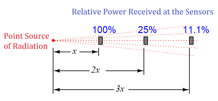
This is a basic physical principle for all kinds of radiation, grounded in simple geometry. If we examine the radiation flux emanating from a point-source, we find that it must spread out as it travels in straight lines, and that the spreading-out happens at a rate defined by the square of the distance. An analogy for this phenomenon is to imagine a spherical latex balloon expanding as air is blown into it. The surface area of the balloon is proportional to the square of its radius. Likewise, the radiation flux emanating from a point-source spreads out in straight lines, in all directions, reaching a total area proportional to the square of the distance from the point (center). The total flux measured as a sphere will be the same no matter what the distance from the point-source, but the area it is divided over increases with the square of the distance, and so any object of fixed area backing away from a point-source of radiation encounters a smaller and smaller fraction of that flux.
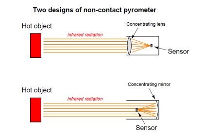
If non-contact pyrometers really were “looking” at a point-source of infrared radiation, their signals would indeed decrease with distance. The saving grace here is that non-contact pyrometers are focused-optic devices, with a definite field of view, and that field of view should always be completely filled by the target object (assumed to be at a uniform temperature). As distance between the pyrometer and the target object changes, the cone-shaped field of view covers a surface area on that object proportional to the square of the distance Backing the pyrometer away to twice the distance increases the viewing area on the target object by a factor of four; backing away to three times the distance increases the viewing area nine times:
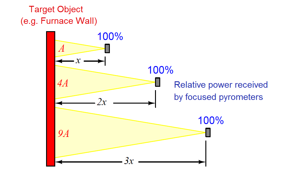
So, even though the inverse square law correctly declares that radiation emanating from the hot wall (which may be thought of as a collection of point-sources) decreases in intensity with the square of the distance, this attenuation is perfectly balanced by an increased viewing area of the pyrometer. Doubling the separation distance does result in the flux from any given point on the wall spreading out by a factor of four, but the pyrometer now sees four times as many similar points on the wall as it did previously. So long as all the points within the field of view are uniform in temperature, the result is a perfect cancellation with the pyrometer providing the exact same temperature measurement at any distance from the target.
If the sensor’s field of view expands far enough to capture objects other than the one whose temperature we intend to measure, measurement errors will result. The sensor will now yield a weighted average of all objects within its field of view, and so it is important to ensure that field is limited to cover just the object we intend to measure.
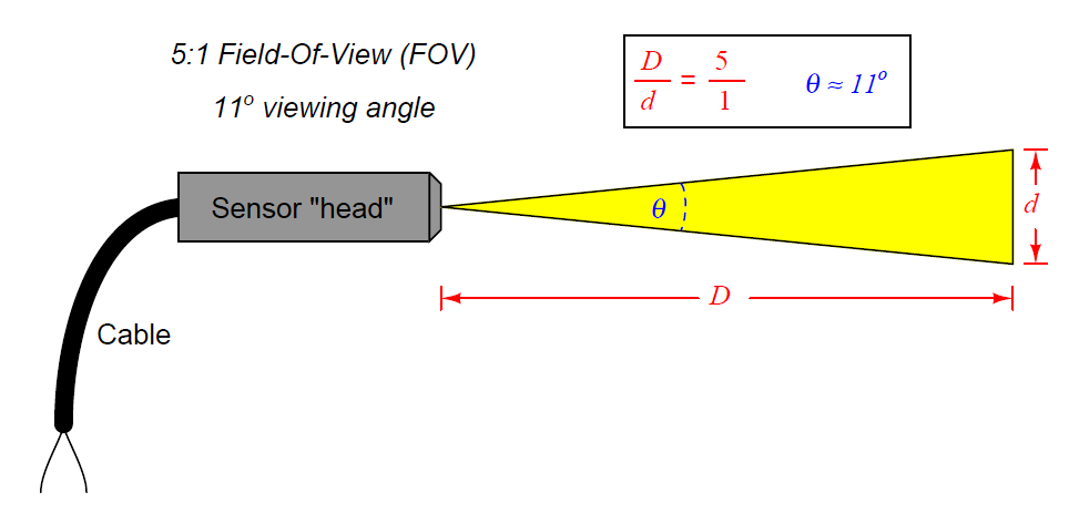
Non-contact sensor fields-of-view are typically specified either as an angle, as a distance ratio, or both. For example, the following illustration shows a non-contact temperature sensor with a 5:1 (approximately 11o) field of view:
The mathematical relationship between viewing angle (θ) and distance ratio (D/d) follows the tangent function:
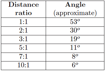
A sampling of common field-of-view distance ratios and approximate viewing angles appears in this table:
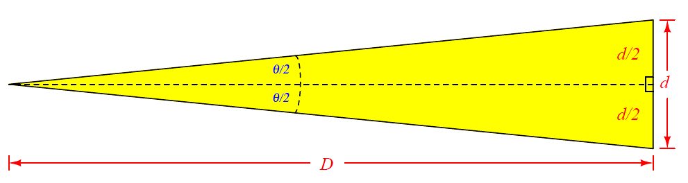
A trigonometric explanation for these equations is shown in the following diagram, where the isosceles field-of-vision triangle is split into two “right” triangles, each one having an adjacent side length of D and an opposite side length of d/2 for angle θ/2:
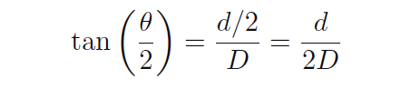
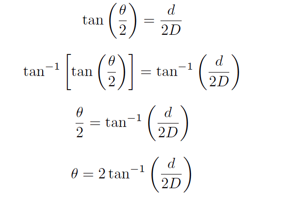
Since we know the tangent function is the ratio of opposite to adjacent side lengths for a right triangle, this means the tangent of the half-angle (θ/2) will be equal to the ratio of the opposite side length (d/2) to the adjacent side length (D):
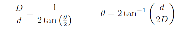
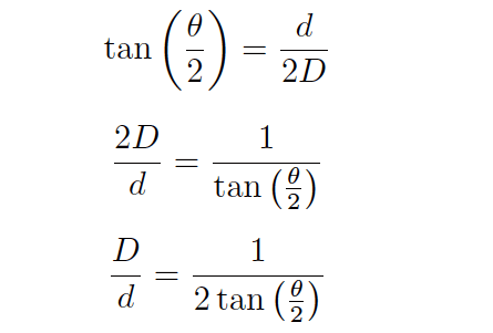
Solving for the length ratio D/d is now just a matter of algebraically manipulating this equation:
Solving for the viewing angle (θ) requires another form of manipulation on the basic tangent equation, where we “un-do” the tangent function by using the inverse tangent (or “arctangent”) function:
Emissivity
Aside from their inherent nonlinearity, perhaps the main disadvantage of non-contact temperature sensors is their inaccuracy. The emissivity factor (e) in the Stefan-Boltzmann equation varies with the composition of a substance, but beyond that there are several other factors (surface finish, shape, etc.) that affect the amount of radiation a sensor will receive from an object. For this reason, emissivity is not a very practical way to gauge the effectiveness of a non-contact pyrometer. Instead, a more comprehensive measure of an object’s “thermal-optical measureability” is emittance.
A perfect emitter of thermal radiation is known as a blackbody. Emittance for a blackbody is unity (1), while emittance figures for any real object is a value between 1 and 0. The only certain way to know the emittance of an object is to test that object’s thermal radiation at a known temperature. This assumes we have the ability to measure that object’s temperature by direct contact, which of course renders void one of the major purposes of non-contact thermometry: to be able to measure an object’s temperature without having to touch it. Not all hope is lost, though: all we have to do is obtain an emittance value for that object one time, and then we may calibrate any non-contact pyrometer for that object’s particular emittance so as to measure its temperature in the future without contact.
Beyond the issue of emittance, other idiosyncrasies plague non-contact pyrometers. Objects also have the ability to reflect and transmit radiation from other bodies, which taints the accuracy of any non-contact device sensing the radiation from that body. An example of the former is trying to measure the temperature of a silver mirror using an optical pyrometer: the radiation received by the pyrometer is mostly from other objects, merely reflected by the mirror. An example of the latter is trying to measure the temperature of a gas or a clear liquid, and instead primarily measuring the temperature of a solid object in the background (through the gas or liquid).
Nevertheless, non-contact pyrometers have been and will continue to be useful in specific applications where other, contact-based temperature measurement techniques are impractical.
Credits : Tony R. Kuphaldt – Creative Commons Attribution 4.0 License