Inst ToolsInst ToolsInst Tools
  • Courses
  • Automation
    • PLC
    • Control System
    • Safety System
    • Communication
    • Fire & Gas System
  • Instrumentation
    • Design
    • Pressure
    • Temperature
    • Flow
    • Level
    • Vibration
    • Analyzer
    • Control Valve
    • Switch
    • Calibration
    • Erection & Commissioning
  • Interview
    • Instrumentation
    • Electrical
    • Electronics
    • Practical
  • Q&A
    • Instrumentation
    • Control System
    • Electrical
    • Electronics
    • Analog Electronics
    • Digital Electronics
    • Power Electronics
    • Microprocessor
  • Request
Search
  • Books
  • Software
  • Projects
  • Process
  • Tools
  • Basics
  • Formula
  • Power Plant
  • Root Cause Analysis
  • Electrical Basics
  • Animation
  • Standards
  • 4-20 mA Course
  • Siemens PLC Course
Reading: Loop Powered Pressure Transmitter
Share
Font ResizerAa
Inst ToolsInst Tools
Font ResizerAa
  • Courses
  • Design
  • PLC
  • Interview
  • Control System
Search
  • Courses
  • Automation
    • PLC
    • Control System
    • Safety System
    • Communication
    • Fire & Gas System
  • Instrumentation
    • Design
    • Pressure
    • Temperature
    • Flow
    • Level
    • Vibration
    • Analyzer
    • Control Valve
    • Switch
    • Calibration
    • Erection & Commissioning
  • Interview
    • Instrumentation
    • Electrical
    • Electronics
    • Practical
  • Q&A
    • Instrumentation
    • Control System
    • Electrical
    • Electronics
    • Analog Electronics
    • Digital Electronics
    • Power Electronics
    • Microprocessor
  • Request
Follow US
All rights reserved. Reproduction in whole or in part without written permission is prohibited.
Inst Tools > Blog > Practical Questions > Loop Powered Pressure Transmitter

Loop Powered Pressure Transmitter

Last updated: May 22, 2020 12:32 pm
Editorial Staff
Practical Questions
No Comments
Share
2 Min Read
SHARE

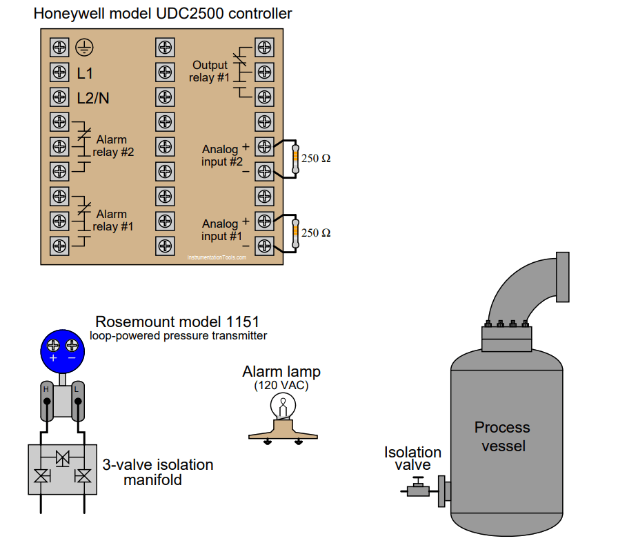
This Honeywell model UDC2500 controller needs to connect to a loop-powered pressure transmitter in such a way that it displays the amount of pressure in the process vessel, and outputs a signal to the 120 VAC alarm lamp if the process pressure becomes too great/high.

Alarm relay #1 in the controller has been configured for a high-pressure trip point of 140 PSI:

Loop Powered Pressure Transmitter
Honeywell Controller

Sketch all necessary connecting wires and tubes to make this a working system. Note: you will need to add electrical power sources to the diagram!

Also, identify the proper open/closed state for each hand valve contained in the pressure transmitter’s three-valve isolation manifold.

Solution:

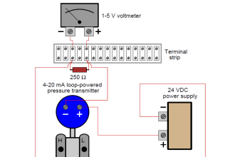
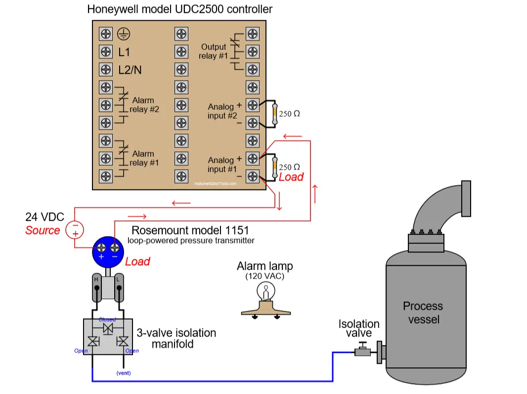
The below figure shows you the connections for the pressure transmitter and a external source.

Share with you how do you cannect the alarm lamp?

Loop Powered Pressure Transmitter

More Questions:

1. A problem-solving technique useful for making proper connections in pictorial circuit diagrams is to first identify the directions of all DC currents entering and exiting component terminals, as well as the respective voltage polarity marks (+,−) for those terminals, based on your knowledge of each component acting either as an electrical source or an electrical load.

Discuss and compare how these arrows and polarity marks (refer above picture) simplify the task of properly connecting wires between components.

2. Supposing the transmitter outputs a current value of 14 mA, calculate all voltage drops in this circuit.

3. The pressure transmitter configured 0 to 10 bar range. What is the pressure reading of transmitter when the loop-current is 11mA?

4. The pressure transmitter displays a reading of 3.5 bar. What is the loop-current?

Share your answers with us through below comments section.

Read Next:

  • Level Control using Flow Loop
  • Question on Analytical Controller
  • Digital to Analog Conversion
  • Differential Pressure Transmitter
  • Pressure Transmitter Circuit

Credits: Tony R. Kuphaldt
Don't Miss Our Updates
Be the first to get exclusive content straight to your email.
We promise not to spam you. You can unsubscribe at any time.
Invalid email address
You've successfully subscribed !

Continue Reading

Determine the Status of Lamps and Relays in the Circuit ?
Analyze the Relay Circuit and Find the Status ?
Draw the appropriate Pressure Switch Symbol ?
As per Process Conditions, Find out the Circuit Components Status ?
Practical Process Control System Questions & Answers – 3
Draw Wiring of a Pressure Switch to control two lamps
Share This Article
Facebook Whatsapp Whatsapp LinkedIn Copy Link
Share
Leave a Comment

Leave a Reply Cancel reply

Your email address will not be published. Required fields are marked *

Stay Connected

128.3kFollowersLike
69.1kFollowersFollow
210kSubscribersSubscribe
38kFollowersFollow

Categories

Explore More

LRV and URV of PT for Extreme Limits of Empty and Full
Guided-wave Radar Asset Management Parameters
What Effect on Hydrostatic Level Transmitter if Liquid Density Changes?
Programmable Logic Controller (PLC) Questions and Answers – 10
A Series of False Pressure Alarms
pH Monitoring System Triggers an Alarm
Programmable Logic Controller (PLC) Questions and Answers – 6
Questions on Pressure Transmitter Calibration Setup

Keep Learning

Span of Pressure Gauge

How to Decrease Span of Pressure Gauge?

Calculate the 0%, 50%, and 100% Calibration Points

Calculate the 0%, 50%, and 100% Calibration Points

displacer level transmitter configuration

Displacer Level Transmitter Questions

Pressure Switch Questions

Pressure Switch Questions

Manometer with two different liquids

Calculate the Height of Glycerine

liquid flow control system

Practical Process Control System Questions & Answers – 7

Practical Control Systems Questions & Answers

Practical Process Control System Questions & Answers – 1

hydrostatic interface measurement calculation

Hydrostatic Pressure Measurement Questions

Learn More

O Ring Failure

How O-Ring Failure caused NASA’s shuttle to Blast ?

Industrial Automation Architecture reference model

Industrial Automation System Architecture Reference Model

Power Systems Questions & Answers

Power Systems MCQ Series 17

Do’s and Don'ts in PLC

#18 PLC Best Practices – Store PLC Hard Stop Events from Faults

hazard standards

Hazardous Area Classification markings

Gas Filter Correlation (GFC) spectrometer

Gas Filter Correlation (GFC) Spectroscopy

Pneumatic Training Course - Download PDF

Pneumatic Training Course – Download PDF

RF and RTJ Flange Installed Gasket

Flange Joint Errors shutdowns root cause analyzed and eliminated

Menu

  • About
  • Privacy Policy
  • Copyright

Quick Links

  • Learn PLC
  • Helping Hand
  • Part Time Job

YouTube Subscribe

Follow US
All rights reserved. Reproduction in whole or in part without written permission is prohibited.
Welcome Back!

Sign in to your account

Username or Email Address
Password

Lost your password?