A load cell is a device that is used to measure weight or force. W hen a force is applied to it in a specific manner, a load cell produces an output signal that is proportional to the applied force.
Strain gage load cells are at the heart of the majority of weighing and force measurement devices produced today. One end of a load cell is typically supported on a rigid structure while the other end supports a load-receiving device through which the load or force is applied.
Load cells can be used individually or in combinations in weighing devices, as dictated by the geometry of the object to be weighed.
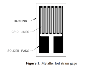
Strain gage load cells are by far the most common form of load cell commercially available today, and are briefly described here. F igure 1 illustrates a typical metallic foil strain gage.
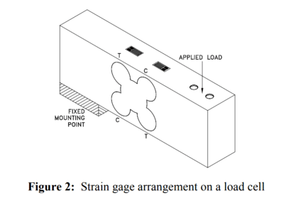
This consists of a metallic foil etched into parallel grid lines forming a circuit between the solder pads that are used to complete the circuit. The foil is bonded to an insulating backing material that, in turn, is bonded to the surface of the load cell, as shown in Figure 2.
A Strain gage type load cell consists of a spring element that is selectively weakened to create regions of relatively high strain; this is where the strain gages are applied.
In Figure 2, two gages are illustrated on the top surface and two corresponding gages on the bottom surface are not shown. In this arrangement two gages measure tensile strains and two measure compressive strains as load is applied to the load cell (indicated by the letters T and C respectively in Figure 2).
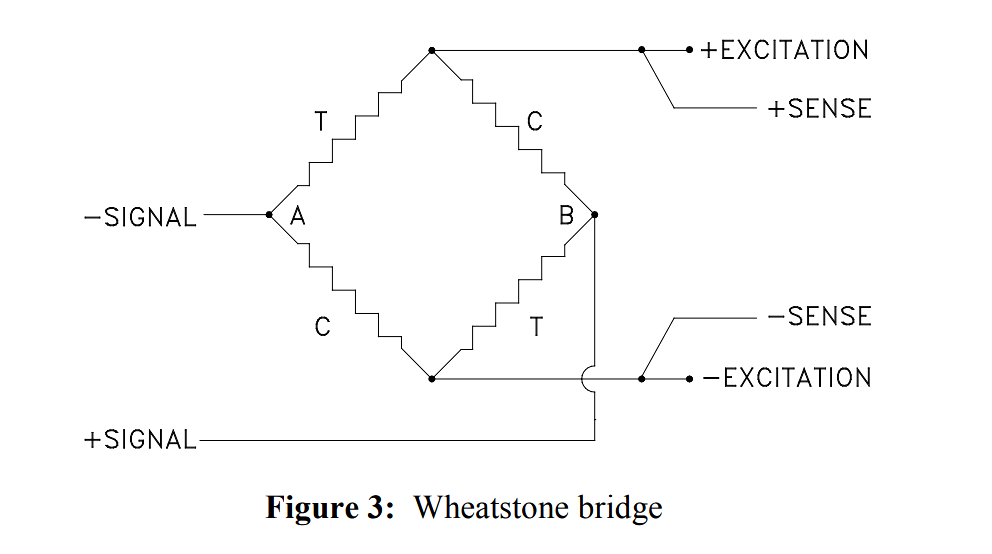
The strain gages are wired together to form a Wheatstone bridge, as illustrated in Figure 3.
Note that several other resistors are typically included in the circuit, for example, a resistor may be added to temperature compensate the cell’s performance, these are not shown for simplicity.
A stable excitation voltage is applied to opposite corners of the Wheatstone bridge, and a signal is measured across the others, points A and B in Figure 3. With no load applied to the cell, all gages have the same resistance and hence there is no voltage difference between points A and B. As load is applied to the cell, the resistance of the tension gages increases, while that of the compression gages decreases.
The bridge now becomes “unbalanced” and a voltage difference (signal) proportional to applied load can be measured across points A and B. E lectronic weight indicators are readily available which, at their most basic, supply the excitation voltage for the bridge, measure the output signal, and provide a digital display of the applied load.
Some load cells and indicators have provision for sense wires as shown in Figure 3 which allow the indicator to measure and adjust for the actual excitation voltage applied to the cell, this is particularly important with long cable runs.
Load Cell Healthiness Checks
When assessing the functionality of a strain gauge load cell, measurement of the following parameters is most helpful.
1. Zero Offset −
With recommended excitation voltage supplied, a zero load output greater than the manufacturer’s specification is a good indication that the load cell may have been damaged. This is most often a case of overloading and may be either positive or negative. It could also be the result of moisture damage.
2. Zero Instability −
An unstable zero load output is an indication of leakage current being drained from the load cell circuit, most often the result of moisture damage. T his instability will likely be superimposed on the rated output as well.
3. Terminal Resistances −
With the many load cells available on the market, load cell circuit resistances can vary. Though there is no “correct” value for a manufacturer to use, some of the more common are 350 Ω, 700 Ω, 900 Ω, and 1000 Ω. When checking the excitation, you can expect the resistance to be somewhat higher than the internal Wheatstone bridge, due to the addition of compensation networks.
The modulus (spring rate) of load cell spring elements drops with temperature, producing higher outputs as temperature increases. Additionally, most strain gauges used in load cells have gauge factors that increase with temperature. These effects are then attenuated with temperature sensitive resistors and shunts.
Temperature sensors and software correction algorithms on circuitry mounted in the casing of the load cell are another way to compensate for increasing output.
When modulus compensating nickel-chromium (Karma) foil is used to make strain gages, excitation lead readings can then be close to nominal, 350 Ω for example, or slightly higher.
For proper terminal resistance readings between all combinations of excitation and signal wires of a load cell, use the manufacturer’s specifications.
4. Insulation Resistance −
Insulation resistance is a good indication of the integrity of a load cell. L ow insulation resistance can cause instability due to leakage current from the load cell circuit to the base material of the load cell.
Unstable readings and non-repeatability problems when measuring rated output can be indications of low insulation resistance.
To measure insulation resistance, an ohmmeter with measuring capability in the range of giga-ohms is necessary. When new, the resistance between any direct bridge lead and the base metal of the load cell should be 2000 mega-ohms or higher.
Load cells may operate accurately with insulation resistance down in the range of 500 mega-ohms, however instability can begin even before such a low value occurs.
It is recommended that an ohmmeter be used which does not apply more than 50 volts to the circuitry under test.
Generally, the performance characteristics of a load cell are assessed by the following parameters:
- NON-LINEARITY
- HYSTERESIS
- NON-REPEATABILITY
- TEMPERATURE EFFECT ON RATED OUTPUT
- TEMPERATURE EFFECT ON ZERO LOAD OUTPUT
- CREEP & MINIMUM DEAD LOAD OUTPUT RETURN
Tests are designed to provide a quantitative determination of each characteristic
Source : scalemanufacturers.org
