Reset of Integral Action
Most of the processes we will be controlling will have a clearly defined setpoint. If we wish to restore the process to the setpoint after a disturbance then proportional action alone will be insufficient.
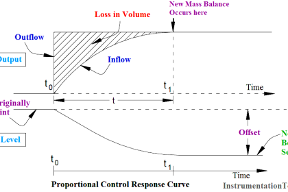
Consider the below Figure showing the response of a system under proportional control.
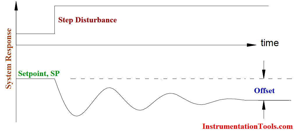
Fig : Response Curve: Proportional Control Only
Note: Here we are discussing the example used in Proportional controller Principle article.
If we wish to restore the process to the setpoint we must increase the inflow over and above that required to restore a mass balance. The additional inflow must replace the lost volume and then revert to a mass balance situation to maintain the level at the setpoint. This is shown in Below Figure. This additional control signal must be present until the error signal is once again zero.
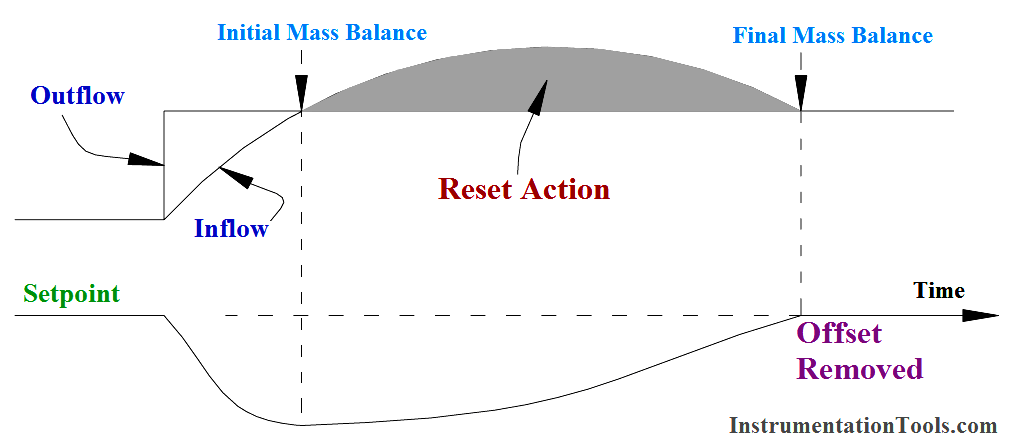
Fig: Additional Control Signal ( I ) Restores Process to Setpoint
This additional control signal is known as Reset action, it resets the process to the setpoint. Reset action is always used in conjunction with proportional action. Mathematically, reset action is the integration of the error signal to zero hence the alternative nomenclature Integral action.
The combination of proportional plus reset action is usually referred to as PI control.
The response of PI control is best considered in open loop form, i.e., the loop is opened just before the final control element so that the control correction is not in fact made. This is illustrated in Below Figure.
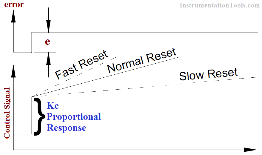
Fig : Proportional Plus Reset, Open Loop Response
It can be seen that proportional action will be equal to ke where k is the gain of the controller. Reset action will cause a ramping of the output signal to provide the necessary extra control action.
After time, say t, the reset action has repeated the original proportional response; this is the repeat time, the unit chosen for defining reset action. It can be seen that increased reset action would increase the slope of the reset ramp.
Note that proportional action occurs first followed by reset action.
Reset action is defined as either reset rate in repeats per minute (RPM) or reset time in minutes per repeat (MPR).
Example:
A direct acting controller has a proportional band of 50% ia subjected to a sustained error. The set point is 50% and the measurement 55%.After 4 minutes the total output signal from the controller has increased by 30%. What is the reset rate setting in RPM and MPR?
PB = 50%
gain, k = 100% / 50% = 2
Since ↑↑ Direct Acting k will be negative
Proportional Signal = -k x error = -2 x -5% = +10%
Total signal after 4 minutes = +30% = P+I
∴Integral Signal = +20%
i.e., integral action has repeated original proportional signal twice in 4 minutes, 2 repeats per 2 minutes or 0.5 repeats per minute.
Reset rate = 0.5 RPM
Reset rate = 1/0.5 RPM = 2.0 MPR
Let us just consider a very slow reset rate and a very fast reset rate.
A very slow reset rate will ramp the control signal up very slowly. Eventually the process will be returned to the setpoint. The control will be very sluggish and if the system is subjected to frequent disturbances the process may not ever be fully restored to the setpoint!
If a very fast reset rate is used, the control signal will increase very quickly. If we are controlling, say, a large volume tank, the level response of the tank may lag behind the response of the controller.
The control signal will go to its limiting value (0 or 100%) and the limiting control signal will eventually cause the process to cross the setpoint. The error signal will now change its sign, and reset action will also reverse direction and quickly ramp to the other extreme.
This process will continue indefinitely, the control valve cycling, with resulting wear and tear, from one extreme to the other. The actual process level will cycle about the setpoint. This cycling is known as reset windup and will occur if the process is subject to a sustained error and a too fast reset rate. The reset rate must be decreased (reset time increased).
The mathematical expression for P + I control becomes:
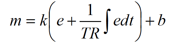
m = control signal
e = error signal
TR = reset time (MPR)
b = bias signal
k = controller gain
(e = SP M) ∴ (+ or -)
For Directing Acting controller, K have Negative sign
For Reverse Acting Controller, K have Positive sign
Proportional control i.e., (proper sign of gain) inputs a 180° lag into the system (the correction must be opposite to the error). Reset action introduces a further lag. This fact must be taken into account when tuning the controller. (It follows proportional action). The total lag must be increased and is now closer to 360°. (360° lag means the feedback signal is now in phase with the input and adding to it the system is now unstable.) Reset action causes the loop to be less stable.
Summary:
- Reset action removes offset.
- Its units are Repeats per Minute (RPM) or Minutes per Repeat (MPR)
- If reset action is faster than the process can respond, Reset Windup can occur.
- Reset Action makes a control loop less stable.