Inst ToolsInst ToolsInst Tools
  • Courses
  • Automation
    • PLC
    • Control System
    • Safety System
    • Communication
    • Fire & Gas System
  • Instrumentation
    • Design
    • Pressure
    • Temperature
    • Flow
    • Level
    • Vibration
    • Analyzer
    • Control Valve
    • Switch
    • Calibration
    • Erection & Commissioning
  • Interview
    • Instrumentation
    • Electrical
    • Electronics
    • Practical
  • Q&A
    • Instrumentation
    • Control System
    • Electrical
    • Electronics
    • Analog Electronics
    • Digital Electronics
    • Power Electronics
    • Microprocessor
  • Request
Search
  • Books
  • Software
  • Projects
  • Process
  • Tools
  • Basics
  • Formula
  • Power Plant
  • Root Cause Analysis
  • Electrical Basics
  • Animation
  • Standards
  • 4-20 mA Course
  • Siemens PLC Course
Reading: Instrumentation Cable trays Installation in vertical orientation
Share
Font ResizerAa
Inst ToolsInst Tools
Font ResizerAa
  • Courses
  • Design
  • PLC
  • Interview
  • Control System
Search
  • Courses
  • Automation
    • PLC
    • Control System
    • Safety System
    • Communication
    • Fire & Gas System
  • Instrumentation
    • Design
    • Pressure
    • Temperature
    • Flow
    • Level
    • Vibration
    • Analyzer
    • Control Valve
    • Switch
    • Calibration
    • Erection & Commissioning
  • Interview
    • Instrumentation
    • Electrical
    • Electronics
    • Practical
  • Q&A
    • Instrumentation
    • Control System
    • Electrical
    • Electronics
    • Analog Electronics
    • Digital Electronics
    • Power Electronics
    • Microprocessor
  • Request
Follow US
All rights reserved. Reproduction in whole or in part without written permission is prohibited.
Inst Tools > Blog > Instrumentation Design > Instrumentation Cable trays Installation in vertical orientation

Instrumentation Cable trays Installation in vertical orientation

Last updated: October 2, 2017 12:26 pm
Editorial Staff
Instrumentation Design
No Comments
Share
2 Min Read
SHARE

The article describes a improvement for better life and easy maintenance for instrumentation cable trays for industry. The practices if applied can be a better choice over a traditional approach of installing cable trays.

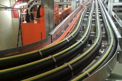
The cable trays are a mean to route the cables to the field destination from control room /MCC to the required field instruments. If we see the traditional methods of installation of them, we will find that most of the installed cable trays are laid in horizontal orientation.

Instrumentation Cable trays in Horizontal Installation

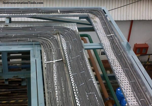
The problems which can be faced in the cable trays in long term are

  1. Accumulation of dust on the tray.
  2. Accumulation of water droplets, if the holes are clogged due to dust and dry leaves and other particles
  3. Chances of ingress of water in cables if the insulation is damaged due to any technical reasons/ageing.
  4. Increased height as layer on layer goes up.
  5. Difficult maintenance and safety risk due to the related heights.

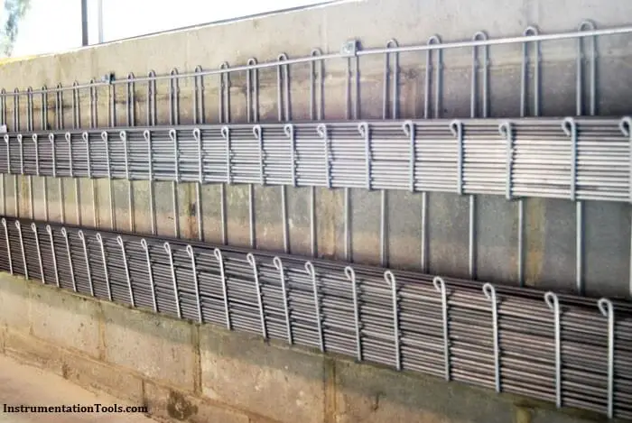
Proposed modification:

The above issues can be minimized to a great extent if we can install the instrumentation cable trays in vertical orientation .Although a little bit higher cost during the installation we can have various long term benefits of

  1. Minimizing the accumulation of dust/foreign particle
  2. Reduced risk of heights as vertical trays can be at same height.

Instrumentation cable trays

The new installations /projects can use the technique in the project stage itself so that they can get maximum benefits and achieving longer life and reduced maintenance cost on account of material and manpower. Similarly old installation can be modified in a phased manner on availability of opportunities like longer shutdown and preventive maintenance schedules .

Article Written by: 

Sh. Pravin V. Maheshkar

Management & technical consultant/trainer  Freelance
Previously Manager –Inst  & Business excellence
(Hindustan zinc ltd ,Echjay steels ltd,total:23 yrs)

Don't Miss Our Updates
Be the first to get exclusive content straight to your email.
We promise not to spam you. You can unsubscribe at any time.
Invalid email address
You've successfully subscribed !

Continue Reading

How-to Create Instrument Loop Diagram (ILD)?
Motor Control Signal Interface
How to Select a pH or ORP Meter
Instrumentation Role during Steam Blowing
Instrument Air Sizing
Level Transmitter and Level Gauge Design Tips
Share This Article
Facebook Whatsapp Whatsapp LinkedIn Copy Link
Share
Leave a Comment

Leave a Reply Cancel reply

Your email address will not be published. Required fields are marked *

Stay Connected

128.3kFollowersLike
69.1kFollowersFollow
210kSubscribersSubscribe
38kFollowersFollow

Categories

Explore More

Package System Architecture – Control & Instrumentation
How to Select a Inductive Proximity Sensor
Temperature Gauges and Elements : Detailed Specifications
Instrument Numbering Philosophy
How to Calculate Transmitter Performance and Calibration Frequency?
Pneumatic Signal Piping and Fittings
Process Design of Instrument Air System
Instrument Air Compressor Control Philosophy

Keep Learning

Cable Trays

Types of Cable Trays – Purpose, Advantages, Disadvantages

Air Cylinder Consumption Calculation for Control Valves

Air Cylinder Consumption Calculation for Control Valves

Instrumentation and Process Control Project Inputs

Instrumentation and Process Teams Interactions in Design Engineering Companies

Testing of Pneumatic Systems

Testing of Pneumatic Systems

Level Instruments

Level Instruments General Specifications

Relay Permissive and interlock circuits

Basics of Permissive and Interlock Circuits

Failure Demand in Safety Control Circuit

Safety Instrumented System Module Failure

process conditions, Find out the Circuit Components Status

As per Process Conditions, Find out the Circuit Components Status ?

Learn More

Electrical Machines Objective Questions

Electrical Machines MCQ Series 10

On-Off Valve Problems

How to Solve On-Off Valve Problems?

Top Electrical Engineering Interview Questions for Freshers

Latest Electrical Motors Questions and Answers

Inverse Time Circuit Breaker

What are Inverse Time and Instantaneous Trip Circuit Breakers?

Create Ladder Diagram from Boolean Logic

Create Ladder Diagram from Boolean Logic

Various Types of Sensors Used in Water Treatment Plant

Various Types of Sensors used in Water Treatment Plant

Allen-Bradley PLC

#15 PLC Best Practices – Safe State when PLC Restarts

Capacitor and Symbols

Capacitance

Menu

  • About
  • Privacy Policy
  • Copyright

Quick Links

  • Learn PLC
  • Helping Hand
  • Part Time Job

YouTube Subscribe

Follow US
All rights reserved. Reproduction in whole or in part without written permission is prohibited.
Welcome Back!

Sign in to your account

Username or Email Address
Password

Lost your password?