The impulse piping is the one which connects the process outputs to the transmitter.

It must convey the process pressure accurately. If for example, the gas collects in a liquid-filled impulse line, or the drain of a gas-filled impulse line becomes plugged, it will not convey the pressure accurately.
Since this will cause errors in measurement output, selecting the proper piping method for the process fluid (gas, liquid or steam) is very important. We discuss below some of the most common routing principles for impulse piping.
In differential pressure transmitters, there is a chance that process fluid (liquid, gas or vapors) may accumulate inside the impulse piping that can cause inaccurate reading of pressures.
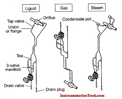
There are three cases as depicted by the figure.
If the process fluid is liquid, the transmitter should be placed lower than the taps.
If the process fluid is gas, the transmitter should be placed higher than the taps.
If the process fluid is steam, it has more chances to vaporize, so we should use condensate pot and the transmitter should be placed at lower level than the taps.
On liquid lines the transmitter is mounted below the orifice plate because liquids have a property of self draining.
On gas service the transmitter is mounted above the orifice plate because Gases have a property of self venting and secondly condensate formation.
On steam service the transmitter is mounted below the orifice plate with condensate pots. The pots should be at the same level.
The conveyor sorting machine is widely used in the packing industries using the PLC program…
Learn the example of flip-flop PLC program for lamps application using the ladder logic to…
In this article, you will learn the STAR DELTA programming using PLC controller to start…
Lube oil consoles of rotary equipment packages in industrial process plants are usually equipped with…
Rotating equipment packages such as pumps, compressors, turbines need the lube oil consoles for their…
This article explains how to blink lights in ladder logic with a detailed explanation video…
View Comments
thank you sir it was very helpful for me , i am waiting for the next lesson
I'm not sure how active the administrator is on this site, but I'm looking for recommendations about situations where customer requirements are not permitting transmitters to be placed below the tap location.
This is because the customer requires that the transmitters be supported by stanchions, and the stanchions must be taller than 0.6 meters.
The pipeline being sensed is sitting at 0.5 meters, so I'm wondering what possible solutions I can consider.
If the service is liquid, transmitter to be located meter below the tapping point because liquid has a property or tendency to self draining.
Inst Tools notes on impulse lines - process leads is better term in my opinion - to steam flow transmitters show condensate pots. These were necessary to reduce flow measurements temporary errors from the by gone days used high volumetric displacement mercury fill float manometers type flow meters during rapid flow changes.
On the other hand present day DPTs volumetric displacement is zero and hence no temporary errors during rapid flow fluctuations. Not providing the condensate pots benefits are:
Enormous Cost Savings by providing a not required expensive item
Far fewer likely leaks fittings
For Clayton Gonsalves
I too firmly believe that liquid and steam measuring instruments should be below the pipelines even if the pipe runs on the floor. One way of complying is dig a 2x2x2m pit with 0.35m tall rain water prevention wall above ground level. Cement the entire pit. Crew should drain the liquid into a bucket and dispose it outside.
A red painted chain barricade prevents persons accidentally falling into the pit. I have done it for a 220-bars liquid ammonia flow DPT. As the liquid NH3 is very pungent I clamped a hose well to the drain to prevent hose pull outs and left the other end in a top full open (No disc) 200 liter barrel 3/4 water fill placed on the ground.
Clamped the hose to the barrel to prevent whips. The drained liquid NH3 instantly evaporates; but being highly water soluble it dissolves in the water. Take the operators' help to dispose off the collection.
Why instrument impulse tube pressure rating is higher than that of pipe pressure rating i.e. 1500# or more?