Inst ToolsInst ToolsInst Tools
  • Ask
  • Courses
  • Videos
  • Q & A
    • Interview
      • Instrumentation
      • Electronics
      • Electrical
      • Practical Questions
    • MCQ
      • Instrumentation MCQ
      • Electrical MCQ
      • Electronics MCQ
      • Control Systems MCQ
      • Analog Electronics MCQ
      • Digital Electronics MCQ
      • Power Electronics MCQ
      • Microprocessor MCQ
      • Multiple Choice Questions
  • EE
    • Electronics
      • Electronics Q & A
      • Electronic Basics
      • Electronic Devices & Circuits
      • Electronics Animation
      • Digital Electronics
    • Electrical
      • Electrical Basics
      • Electrical Q & A
      • Power Electronics
      • Electrical Machines
      • Electrical Animation
      • Power Systems
      • Switchgear & Protection
      • Transmission & Distribution
  • Measure
    • Control Valves
    • Calibration
    • Temperature
    • Pressure
    • Flow
    • Level
    • Analyzers
    • Switches
    • Vibration
    • Solenoid Valve
  • Control
    • PLC Tutorials
    • Control Systems
    • Safety Instrumented System (SIS)
    • Communication
    • Fire & Gas System
  • More
    • Design
    • Tools
    • Animation
    • Basics
    • Formulas
    • Standards
    • TextBooks
    • Common
    • Software
    • Excel Tools
    • Erection & Commissioning
    • Process Fundamentals
    • Videos
    • Books
Search
All rights reserved. Reproduction in whole or in part without written permission is prohibited.
Reading: Impulse Line Purging and Close Coupling of Instruments
Share
Notification Show More
Font ResizerAa
Inst ToolsInst Tools
Font ResizerAa
  • Courses
  • PLC Tutorials
  • Control Systems
Search
  • Ask
  • Courses
  • Videos
  • Q & A
    • Interview
    • MCQ
  • EE
    • Electronics
    • Electrical
  • Measure
    • Control Valves
    • Calibration
    • Temperature
    • Pressure
    • Flow
    • Level
    • Analyzers
    • Switches
    • Vibration
    • Solenoid Valve
  • Control
    • PLC Tutorials
    • Control Systems
    • Safety Instrumented System (SIS)
    • Communication
    • Fire & Gas System
  • More
    • Design
    • Tools
    • Animation
    • Basics
    • Formulas
    • Standards
    • TextBooks
    • Common
    • Software
    • Excel Tools
    • Erection & Commissioning
    • Process Fundamentals
    • Videos
    • Books
Follow US
All rights reserved. Reproduction in whole or in part without written permission is prohibited.
Inst Tools > Blog > Pressure Measurement > Impulse Line Purging and Close Coupling of Instruments

Impulse Line Purging and Close Coupling of Instruments

Impulse lines have high installation and maintenance costs, leaks and it is possible to eliminate these problems by using close coupling.

Last updated: September 28, 2022 2:33 pm
R Jagan Mohan Rao
Pressure Measurement
No Comments
Share
5 Min Read
SHARE

By measuring the differential pressure across the flow elements like orifice, annubar, pitot tube, venturi, or other primary sensing devices, process flow measurements can be carried out.

Contents
What Causes Impulse Pipe Lines to get Plugged?Close CouplingAdvantages of Close CouplingLimitations in using Close Coupling

After contamination of fluid, if the flow sensor element clogs up or if it crystallizes, what happens to the impulse lines or sensor lines?

In the above two instances, causes large errors in the measurement of differential pressure.

In one solution, a flow of fluid can be introduced down the sensing lines and into the process flow. Purging of impulse pipeline eliminates stagnant fluid, which is a common source of the problem. The fluid can be liquid or gas that is inert to the process. Otherwise, it can be a small amount of actual process fluid.

Isolation of transmitters and flushing of the impulse lines is a common solution to solve the problem.

What Causes Impulse Pipe Lines to get Plugged?

  • In case preventive maintenance routines are reduced, the chances of impulse line plugging happens. For example – Schedule four PM activities per year in a peculiar process plant, if it is reduced to two, the possibility of plugging in impulse lines can not be ruled out.
  • Process upsets – Differential temperatures, and other outs accomplishing process phase change are very rare cases in process industries, particularly in chemical plants. It may prove to be catastrophic.
  • Differential temperatures or other outputs accomplish process phase change.
Impulse Line Purging and Close Coupling

Close Coupling

The compact mount manifold is an option that allows us to further simplify the design. If any application permits it, then this is a magnificent and simple solution.

Impulse lines can have high installation and maintenance costs, as well as challenges such as blockages, leak points, temperature control, and corrosion. It is possible to eliminate these problems by using a method called close coupling or close mounting, which eliminates lengthy impulse lines.

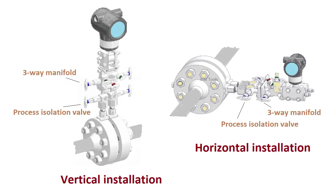
The process interface valve (PIV) and manifold become one unit, and the transmitter mounts directly on it. The whole integrated assembly is connected to the process line.

The solution is to opt for direct mount installations, but they have certain limitations. In certain installations, process interface valves and manifold blocks are separate but mounted very close to the process lines.

One of the limitations is the temperature. Traditionally, the impulse lines were used to protect the transmitter from the high temperatures of the process lines. A compact installation may not be able to perform if the process line is too hot due to its close proximity to the process lines.

Access is the second limitation. This is because it would not be practical to install a compact system 15 meters high, preventing access to the transmitter for calibration.

The last hurdle is the initial cost. Although a compact installation requires an initial investment, it may prove to be less expensive in the long run.

Advantages of Close Coupling

  • Prevents problems with freezing.
  • Short impulse lines are required to avoid pulsations in impulse lines. The shortest impulse lines are provided by close coupling.
  • Close coupling installation arrangement has remarkable benefits, piping gets greatly simplified.
  • The number of joints is reduced when the close coupling is used. As a result, leak routes at threaded connections and compression fittings are reduced.
  • A remarkable speed of response can be achieved with close coupling.
  • There is no need for heating tracing lines, or it is reduced to a minimum.
  • Close coupling eliminates errors caused by different densities of fluid in the separate lines.

Limitations in using Close Coupling

  • Impulse lines may be required when the line temperature is too high or too low for the pressure transmitter.
  • As can be seen in the figure, between the length of pipe and differential pressure transmitter, there is still a length of tapping.
  • Although there is still a length of tapping between the impulse pipe and DP transmitter, it eliminates the requirement for impulse lines in the conventional sense.
Don't Miss Our Updates
Be the first to get exclusive content straight to your email.
We promise not to spam you. You can unsubscribe at any time.
Invalid email address
You've successfully subscribed !
3 Valve Manifold Operation
What is Static Pressure Limit in DP Transmitter ?
Pressure Gauge Selection
C-Bourdon Tube Pressure Gauge Theory
What is Hammer Effect in Gauges ?
Share This Article
Facebook Whatsapp Whatsapp LinkedIn Copy Link
Share
Leave a Comment

Leave a Reply Cancel reply

Your email address will not be published. Required fields are marked *

Stay Connected

128.3kFollowersLike
69.1kFollowersFollow
208kSubscribersSubscribe
38kFollowersFollow

Categories

Recent Comments

  • Guifty Shimica on Top Non-PLC Certification Courses for Automation Professionals
  • Guifty Shimica on Top Non-PLC Certification Courses for Automation Professionals
  • MIHARITSOA Aina Sitraka on Top Non-PLC Certification Courses for Automation Professionals
  • Vaishnavi on Free Instrumentation Course for Trainee Engineers

Related Articles

pressure-gauge-animation

Bourdon Tube Pressure Gauge Working Principle Animation

Force Balance Pressure Transmitters

Pneumatic Pressure Transmitters Principle

Principle of Elastic diaphragm gauges

Elastic Diaphragm Gauge Principle

Components of Bourdon Tube Pressure Gauge

Components of Bourdon Tube – Questions and Answers

Submersible Pressure Transmitter

What is a Submersible Pressure Transmitter? Principle, Advantages

DP transmitter with Manifold

Pressure Transmitter Manifolds

Sealed Bellows Temperature Sensors

Bellows Pressure Sensors Working Principle Animation

U Tube Manometer Principle

U-tube Manometer Principle

More Articles

Difference between Analog Signal and Digital Signal

What are Analog and Digital Signals? Differences, Examples

Pressure Gauge Accessories

Pressure Gauge Accessories

Top 100 PLC Projects List

Top 100 PLC Projects List

PLC Timer Programming Examples – TON, TOF, TP and TONR

Electrical Machines Questions and Answers

Parallel Operation of Single Phase Transformers

Mitsubishi PLC Programming Tutorials

Chromatography Questions & Answers

Liquid Chromatography Questions & Answers

Factors Affecting Inductance

Factors Affecting Inductance

Follow US
All rights reserved. Reproduction in whole or in part without written permission is prohibited.
Welcome Back!

Sign in to your account

Username or Email Address
Password

Lost your password?