The process of downloading and uploading programs in a PLC involves data transfer between a computer and the PLC. In some software, this is referred to as the Write and Read program process. Download/Write refers to sending a program from the computer to the PLC, while Upload/Read refers to retrieving a program from the PLC to the computer. This article will explain how to write and read a program on the FX3U-14MT Lollette PLC using GX-Works2 software.
Required Devices
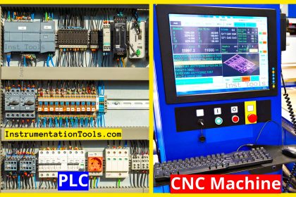
- PLC FX3U-14MT Lollette (China)
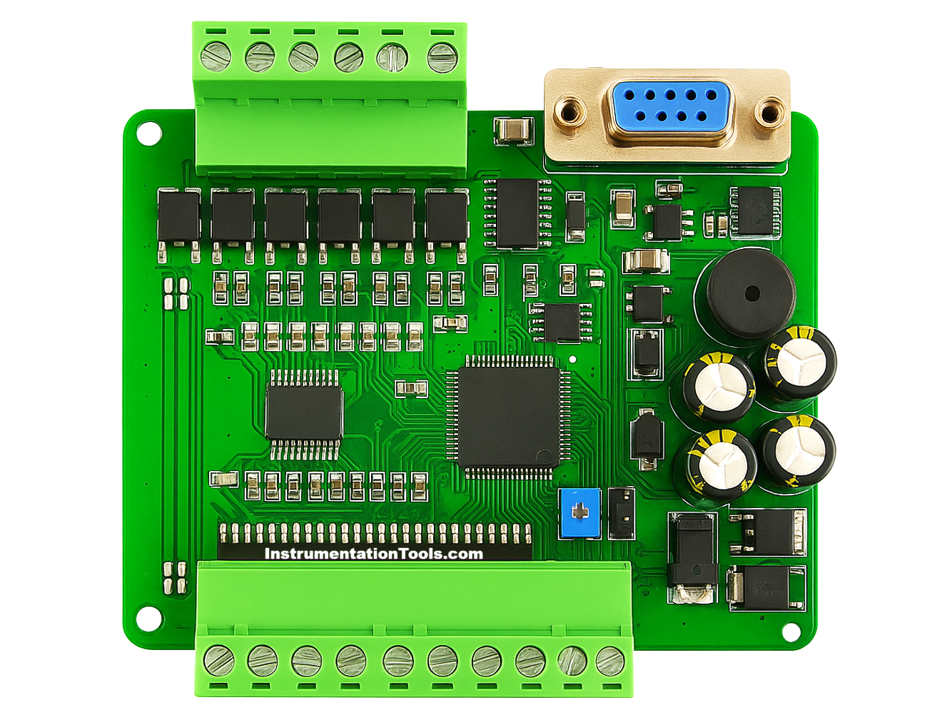
This is a type of industrial PLC with an affordable price, commonly used as a learning tool. It can be programmed using GX-Works2 software and features 8 input contacts, 6 transistor-type output contacts, 3 analog inputs (AI), 3 analog outputs (AO), a 24VDC power supply, and a DB9 female RS232 port for communication between the PLC and a PC. This PLC can only communicate at a speed of 38.4 Kbps.
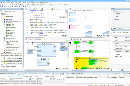
- Software GX Works2
The official programming software from Mitsubishi Electric is used to create, edit, monitor, and debug programs on MELSEC series PLCs (such as FX3U, FX5U, Q-series, and L-series).
- USB to Serial RS232 Cable
A USB to Serial RS-232 cable is an adapter that converts a PC’s USB port into an RS-232 serial port, allowing connection between modern devices (without serial ports) and legacy industrial equipment that only supports RS-232 communication.
How to Write and Read a Program?
In the video below, we have shown you how to do PLC program read and write with real hardware.
Preparation:
- Connect the PLC with 24 VDC power.
- Connect the PLC to the PC using a USB to Serial RS232 cable.
Write PLC Program
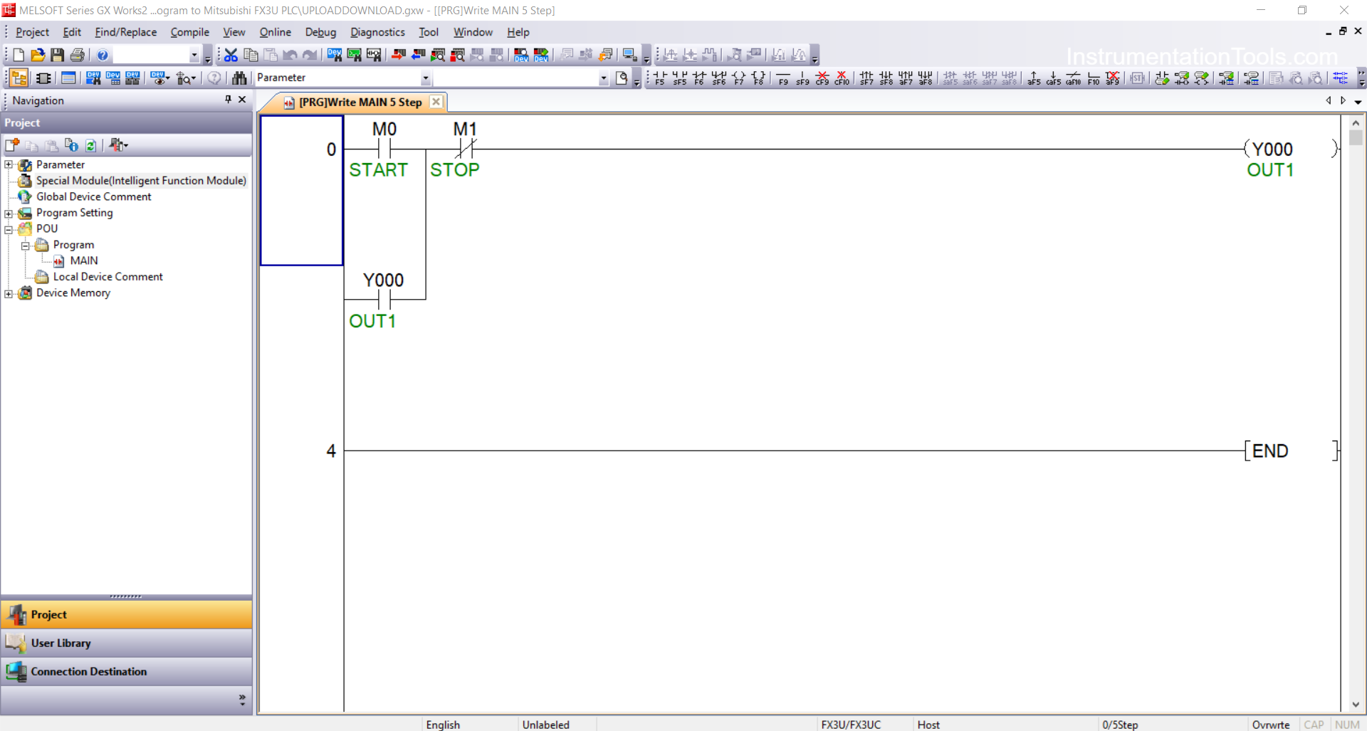
1. Open the project you want to write.
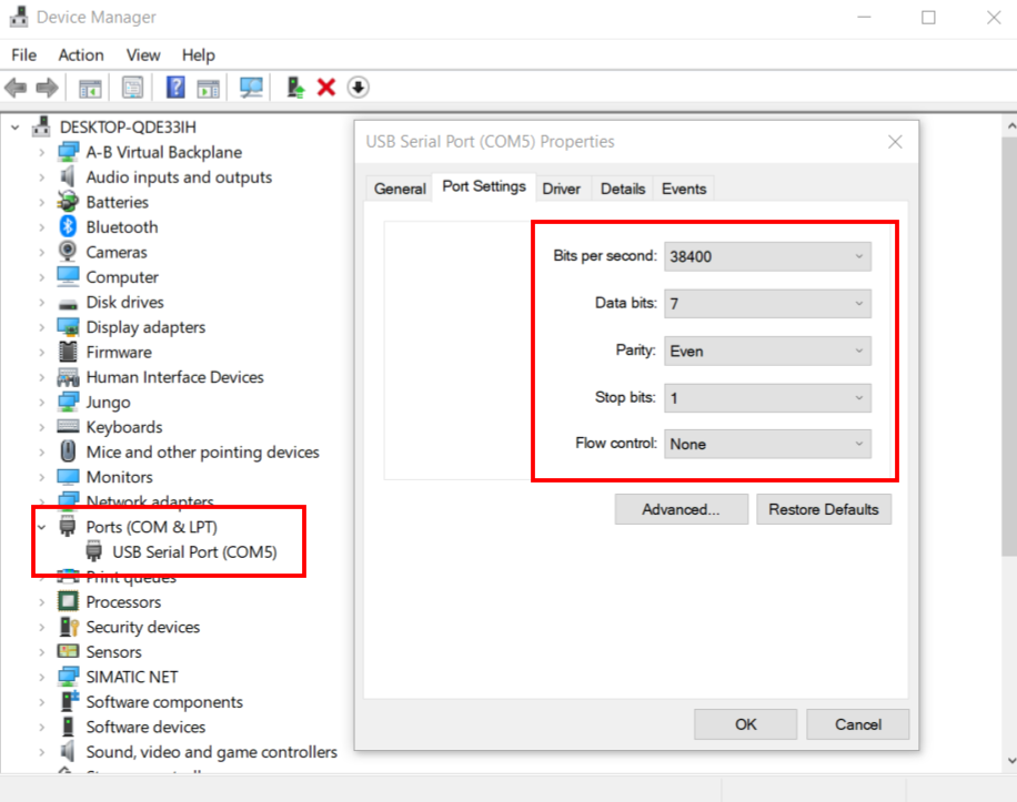
2. Ensure the PLC connection is active by checking the connected port in the Device Manager.
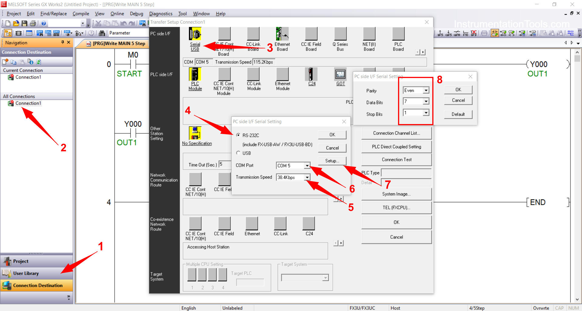
In the image below, the USB to Serial RS-232 cable is connected to Port “5” with the following settings: Bit Per Second “38.4 Kbps”, Data Bits “7”, Parity “Even”, and Stop Bits “1”.
3. Match the PLC communication settings in GX Works2 software with the settings from the Device Manager:
- Connection Detection → Connection1 → Serial USB → RS-232C → COM Port “5”
- Transmission Speed: “38.4 Kbps”
- Setup → Parity: “Even” → Data Bits: “7” → Stop Bits: “1”
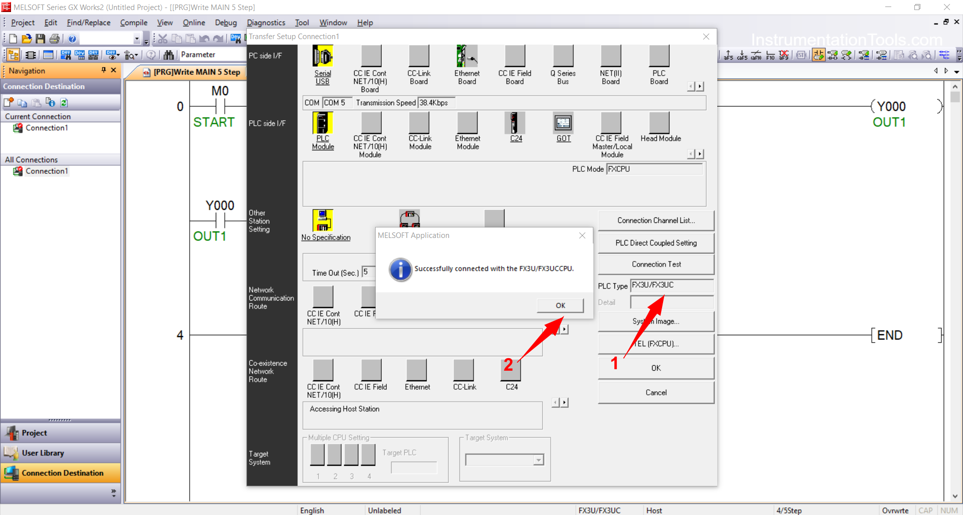
4. Click “Connection Test” to verify that the PC is connected to the PLC. If a pop-up window appears saying “Successfully Connected with the FX3U/FX3UCCPU”, it means the connection is established.
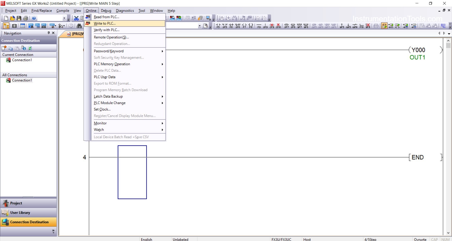
5. Click “Online” → “Write to PLC”.
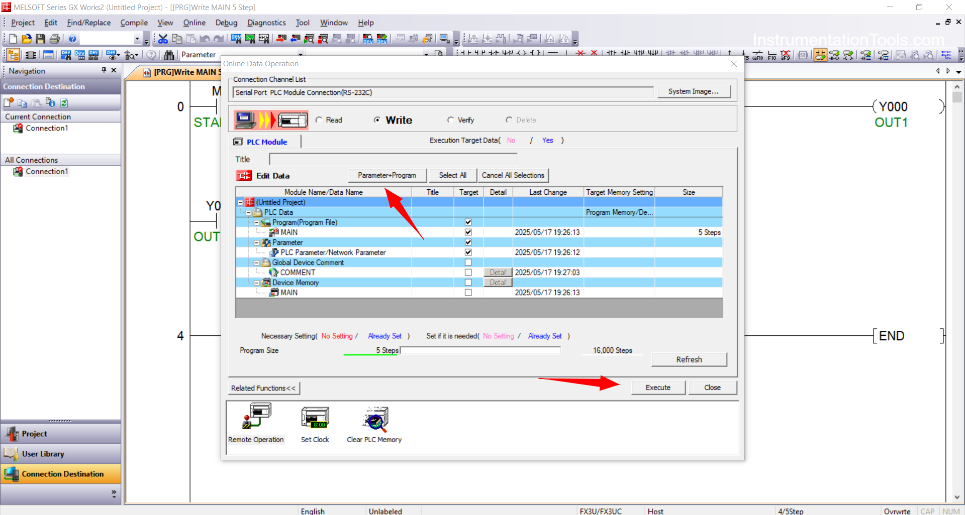
6. Select the parts of the program you want to transfer to the PLC (e.g., Program, Parameters, etc.), then click “Execute”.
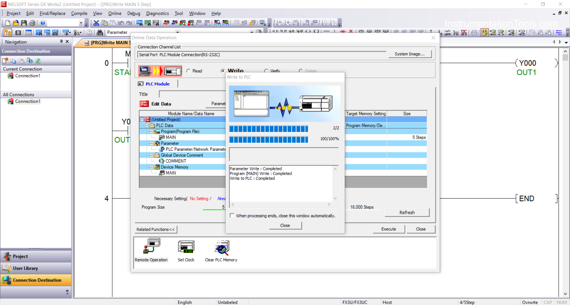
7. If a pop-up window appears as shown below, it indicates the Write process was successful.
Read PLC Program
1. Open GX Works2.
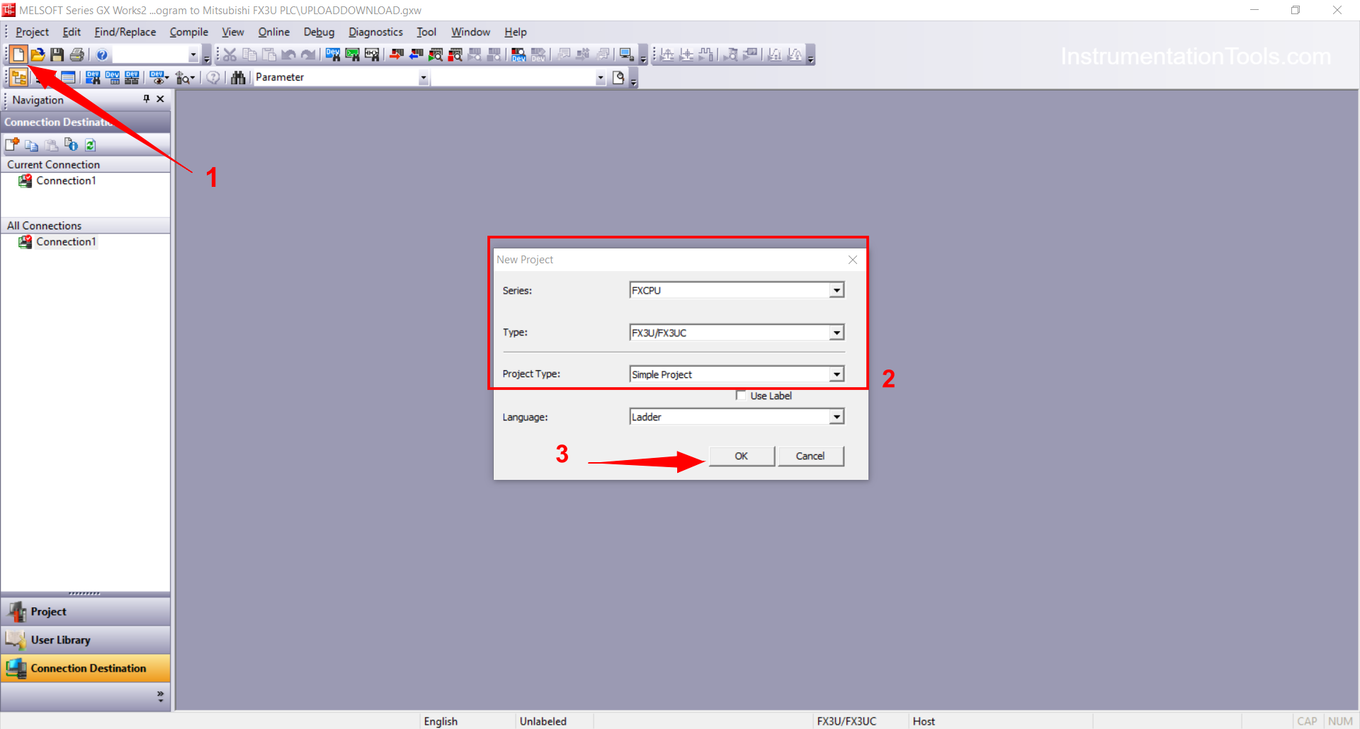
2. Click “Project” → “New” to create a new project. Choose the appropriate PLC type (FX, Q, L) and CPU version. Click “OK”.
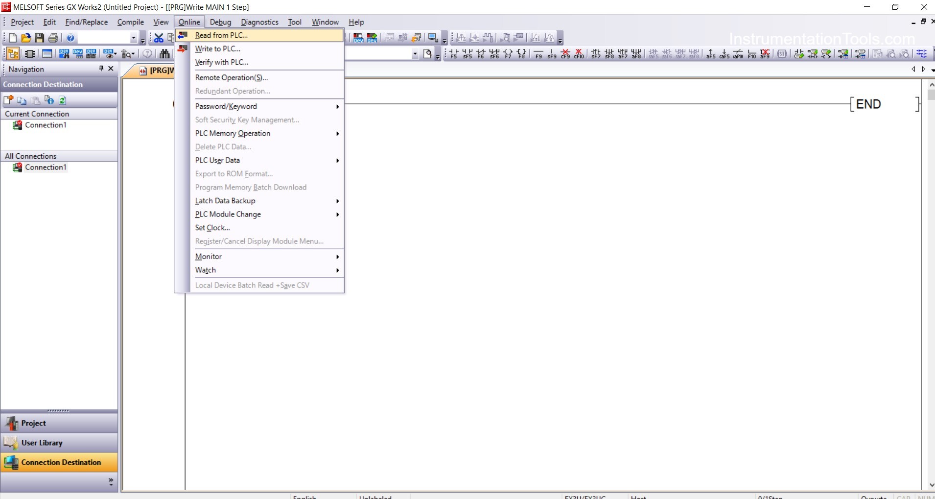
3. Once the project is created, click “Online” → “Read from PLC”.
4. Select the sections you want to read (usually: Program, Parameters, Device Memory, etc.), then click “Execute”.
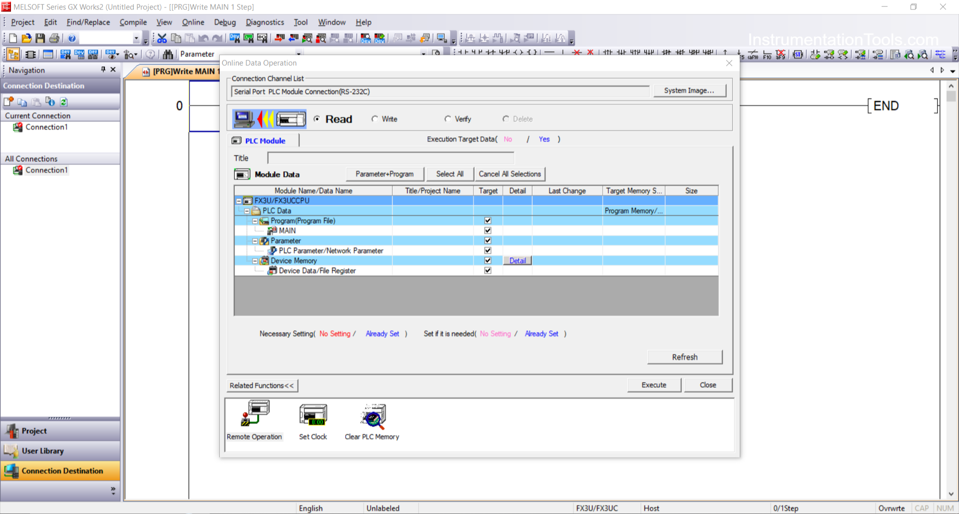
5. The program will be read from the PLC to the PC.
6. Save the project by clicking “File” → “Save As”.
Read Next:
- Analog Input in Mitsubishi FX3U PLC
- Siemens Motor Forward Reverse PLC Logic
- Liquid Flow Control Loop Controller Action
- Traffic Light Auto and Manual PLC Automation
- EasyBuilder Pro Online Simulation of PLC