Inst ToolsInst ToolsInst Tools
  • Courses
  • Automation
    • PLC
    • Control System
    • Safety System
    • Communication
    • Fire & Gas System
  • Instrumentation
    • Design
    • Pressure
    • Temperature
    • Flow
    • Level
    • Vibration
    • Analyzer
    • Control Valve
    • Switch
    • Calibration
    • Erection & Commissioning
  • Interview
    • Instrumentation
    • Electrical
    • Electronics
    • Practical
  • Q&A
    • Instrumentation
    • Control System
    • Electrical
    • Electronics
    • Analog Electronics
    • Digital Electronics
    • Power Electronics
    • Microprocessor
  • Request
Search
  • Books
  • Software
  • Projects
  • Process
  • Tools
  • Basics
  • Formula
  • Power Plant
  • Root Cause Analysis
  • Electrical Basics
  • Animation
  • Standards
  • 4-20 mA Course
  • Siemens PLC Course
Reading: How to Measure capacitance using Multimeter
Share
Font ResizerAa
Inst ToolsInst Tools
Font ResizerAa
  • Courses
  • Design
  • PLC
  • Interview
  • Control System
Search
  • Courses
  • Automation
    • PLC
    • Control System
    • Safety System
    • Communication
    • Fire & Gas System
  • Instrumentation
    • Design
    • Pressure
    • Temperature
    • Flow
    • Level
    • Vibration
    • Analyzer
    • Control Valve
    • Switch
    • Calibration
    • Erection & Commissioning
  • Interview
    • Instrumentation
    • Electrical
    • Electronics
    • Practical
  • Q&A
    • Instrumentation
    • Control System
    • Electrical
    • Electronics
    • Analog Electronics
    • Digital Electronics
    • Power Electronics
    • Microprocessor
  • Request
Follow US
All rights reserved. Reproduction in whole or in part without written permission is prohibited.
Inst Tools > Blog > Electronic Basics > How to Measure capacitance using Multimeter

How to Measure capacitance using Multimeter

Last updated: April 27, 2017 4:22 am
Editorial Staff
Electronic Basics
No Comments
Share
5 Min Read
SHARE

A multimeter determines capacitance by charging a capacitor with a known current, measuring the resulting voltage, then calculating the capacitance.

Warning: A good capacitor stores an electrical charge and may remain energized after power is removed. Before touching it or taking a measurement, a) turn all power OFF, b) use your multimeter to confirm that power is OFF and c) carefully discharge the capacitor by connecting a resistor across the leads (as noted in the next paragraph). Be sure to wear appropriate personal protective equipment.

To safely discharge a capacitor: After power is removed, connect a 20,000 Ω, 5-watt resistor across the capacitor terminals for five seconds. Use your multimeter to confirm the capacitor is fully discharged.

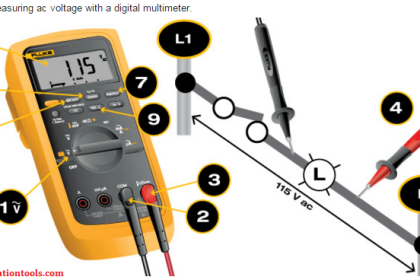
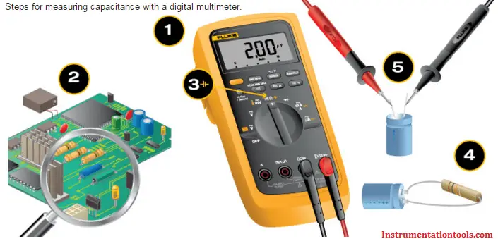
  1. Use your digital multimeter (DMM) to ensure all power to the circuit is OFF. If the capacitor is used in an ac circuit, set the multimeter to measure ac voltage. If is used in a dc circuit, set the DMM to measure dc voltage.
  2. Visually inspect the capacitor. If leaks, cracks, bulges or other signs of deterioration are evident, replace the capacitor.
  3. Turn the dial to the Capacitance Measurement mode ( Capacitor ). The symbol often shares a spot on the dial with another function. In addition to the dial adjustment, a function button usually needs to be pressed to activate a measurement. Consult your multimeter’s user manual for instructions.
  4. For a correct measurement, the capacitor will need to be removed from the circuit. Discharge the capacitor as described in the warning above.Note: Some multimeters offer a Relative (REL) mode. When measuring low capacitance values, the Relative mode can be used to remove the capacitance of the test leads. To place a multimeter in Relative mode for capacitance, leave the test leads open and press the REL button. This removes the residual capacitance value of the test leads.
  5. Connect the test leads to the capacitor terminals. Keep test leads connected for a few seconds to allow the multimeter to automatically select the proper range.
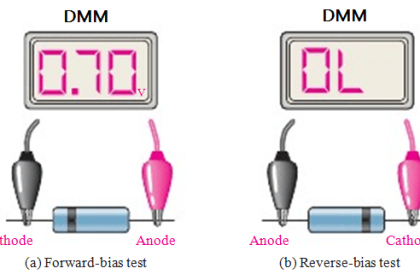
  6. Read the measurement displayed. If the capacitance value is within the measurement range, the multimeter will display the capacitor’s value. It will display OL if a) the capacitance value is higher than the measurement range or b) the capacitor is faulty.

Measure Capacitance using Multimeter

Capacitance measurement overview

Troubleshooting single-phase motors is one of the most practical uses of a digital multimeter’s Capacitance Function.

A capacitor-start, single-phase motor that fails to start is a symptom of a faulty capacitor. Such motors will continue to run once operating, making troubleshooting tricky. Failure of the hard-start capacitor for HVAC compressors is a good example of this problem. The compressor motor may start, but soon overheat resulting in a breaker trip.

Single-phase motors with such problems and noisy single-phase motors with capacitors require a multimeter to verify properly functioning capacitors. Almost all motor capacitors will have the microfarad value marked on the capacitor.

Three-phase power factor correction capacitors are typically fuse protected. Should one or more of these capacitors fail, system inefficiencies will result, utility bills will most likely increase and inadvertent equipment trips of may occur. Should a capacitor fuse blow, the suspected faulty capacitor microfarad value must be measured and verified it falls within the range marked on the capacitor.

Some additional factors involving capacitance are worth knowing:

  • Capacitors have a limited life and are often the cause of a malfunction.
  • Faulty capacitors may have a short circuit, an open circuit or may physically deteriorate to the point of failure.
  • When a capacitor short circuits, a fuse may blow or other components may be damaged.
  • When a capacitor opens or deteriorates, the circuit or circuit components may not operate.
  • Deterioration can also change the capacitance value of a capacitor, which can cause problems.

Source : Fluke

Don't Miss Our Updates
Be the first to get exclusive content straight to your email.
We promise not to spam you. You can unsubscribe at any time.
Invalid email address
You've successfully subscribed !

Continue Reading

Power Supply Circuit Fault Analysis
Zener Diode Voltage Regulators
Basics of Voltage Regulator
What is Contactor ?
What is Cathode Ray oscilloscope ?
How to Test a Transistor ?
Share This Article
Facebook Whatsapp Whatsapp LinkedIn Copy Link
Share
Leave a Comment

Leave a Reply Cancel reply

Your email address will not be published. Required fields are marked *

Stay Connected

128.3kFollowersLike
69.1kFollowersFollow
210kSubscribersSubscribe
38kFollowersFollow

Categories

Explore More

Difference Between Electrical and Electronic Devices
Things to Know When Measuring Current
Types of Noise in Electronics
Electrical Static Grounding Techniques
Top 555 Timer Projects for Engineering Students
IEC labelling for Resistors Color Code
Types of Potentiometers – What is a Potentiometer? – Applications
How to measure frequency using Multimeter

Keep Learning

Top Beginner Soldering Mistakes

Top Beginner Soldering Mistakes and How to Avoid Them?

Seven Segment LED Display

Difference Between Common Cathode and Common Anode 7 Segment LED Display?

Transistor as Switch Working Animation

How a Transistor Switch Works

Power Supply Voltage Regulator Problem

Troubleshooting a Power Supply Circuit

Difference Between Clamp Meters and Digital Multimeters

Difference Between Clamp Meters and Multimeters

Diode-testing-with-multimeter

How to Test a Diode using Multimeter

What is a Non-Linear Device

What is a Non-Linear Device? Example – Advantages

Difference Between LDR and Photodiode

Difference Between LDR and Photodiode

Learn More

Differential Pressure Sensor Calibration

Differential Pressure Sensors Calibration Procedure

Door Lock with Delay PLC Exercise Problems

Door Lock with Delay PLC Exercise Problems

Electrical Contactor, Switch, Circuit Breaker

Electrical Contactor, Switch, Circuit Breaker

Difference between Compact PLC and Modular PLC

Difference between Compact PLC and Modular PLC

What is an Orifice Flange ?

What is an Orifice Flange? – Purpose and Applications

potentiometric level measurement principle

Potentiometric Level Measurement Principle

Power Electronics Objective Questions

Single Phase Voltage Source Inverter MCQ

Measuring process vessel clogging

DP Transmitter Applications

Menu

  • About
  • Privacy Policy
  • Copyright

Quick Links

  • Learn PLC
  • Helping Hand
  • Part Time Job

YouTube Subscribe

Follow US
All rights reserved. Reproduction in whole or in part without written permission is prohibited.
Welcome Back!

Sign in to your account

Username or Email Address
Password

Lost your password?