All pH electrodes require periodic calibration at certain intervals to ensure accurate, repeatable measurements.
A two-point calibration procedure characterizes an electrode with a particular pH meter.
Once an electrode is characterized the electrode-meter pair can be used to find out the pH of a solution.
When a pH sensor is placed in a solution, whose pH is to be measured, an electrochemical reaction takes place. A low voltage (mV) signal is generated and measured by the probe to the analyzer/transmitter.
The potential difference between the reference electrode and measurement electrode is pH. In combination electrodes, both reference electrode and measuring electrode are available in one body.
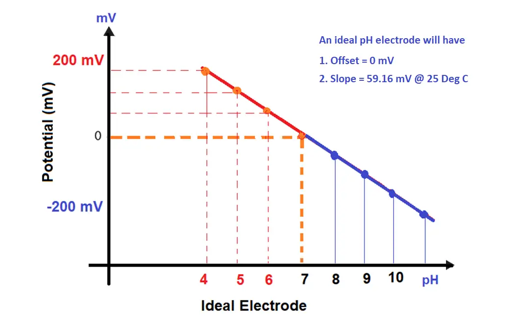
Internally, the analyzer “draws a line” based on the input values. This “line” is the pH curve. The analyzer plots points on the line that corresponds to input signal levels. The offset in the pH slope ( mV versus pH) indicates the damaged electrode.
A 7 pH buffer will produce a 0 mV signal, the slope of the line is 59.16 mV. For every change in the pH unit, the pH sensor change its output by 59 mV.
4 pH buffer will produce a 177.48 mV signal, it is our calibration span point. -177.48 mV signal for 10pH buffer (if three-point calibration is carried out).
The analyzer calculates this information, “connecting the dots” with its program provides the electrode calibration curve.
The analyzer also does the relay activation or current output. The relay outputs can be used to operate pumps, 4-20 mA for the regulation of valves in pH control.
The step-by-step procedure described below to perform a two-point calibration on the pH electrode.
A 7.00 pH and a 4.00 pH buffer solutions are required.
Step 1:
Rinse the electrode thoroughly in de-mineralized (DM) water beaker to remove all traces of the previous test solution.
Note:
Thoroughly rinse the electrode after each buffer test to prevent carry-over traces of contamination of the pH buffer solutions.
Gently clean the electrode on soft tissue to remove the excess rinse water.
Do not rub the bulb since it can cause damage to the electrode bulb or even cause a static charge build-up.
Step 2:
Rinse the electrode and the automatic temperature compensator (ATC) in a 7.00 pH buffer solution.
Allow 30 seconds for the electrode/ATC to reach thermal equilibrium and stable reading with the buffer solution.
Adjust the pH meter with the standardized/Zero control for a pH indication equal to 7.00.
Note:
if the meter does not have an automatic temperature compensation (ATC), place a thermometer along with the electrode in the 7.00 pH solution.
Allow 30 seconds for the pair to get stabilized with the buffer.
Adjust the temperature knob on the meter to correspond with the thermometer reading. Then adjust the pH indication equal to 7.00.
Step 3:
Repeat Step 1 and insert the electrode and the ATC in a 4.00 buffer solution.
Allow 30 seconds for reading to get stabilized before adjusting the pH meter with the slope/span control for a pH indication equal to 4.00.
Step 4:
Repeat Steps 2 and 3 to improve the precision of the calibration.
Read Next:
In the PLC timer application for security camera recording, when motion is detected then camera…
In this example, we will learn batch mixing with PLC ladder logic program using timer…
This PLC example on manufacturing line assembly is an intermediate-level PLC program prepared for the…
In this article, you will learn the PLC programming example with pushbutton and motor control…
This article teaches how to convert Boolean logic to PLC programming ladder logic with the…
In this article, you will learn the PLC programming example on timers function block using…
