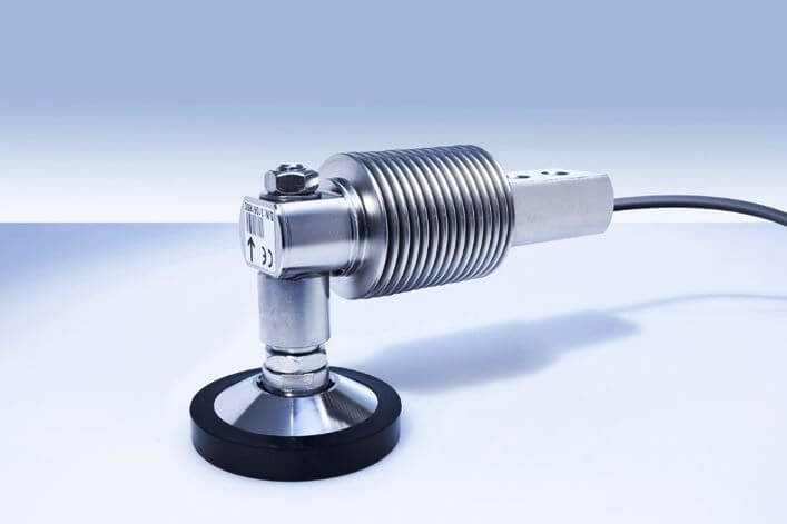
Load cells are special force transducers used for measuring weight or force in various applications. These are integral to weighing systems in various industries, including aerospace, marine, automotive. The reason being they produce highly accurate load measurement data. That is why it is essential to inspect and calibrate them routinely.
Weighing scale calibration services ensure accurate load cell readings and help identify operational issues so that negative consequences can be prevented.

Load cells show signs of wear and tear over a period of years. Frequency of use, environmental causes such as temperature, and aging are some of the contributing factors to the deterioration of load cells.
Faulty cables and instruments, particle accumulation and matter buildup, mechanical defects, incorrect installation, and the influence of electricity can also lead to inefficiency.
That is why routine calibrations should be performed to ensure the efficiency and accuracy of load cells. In the absence of frequent calibrations, load cells can give incorrect readings and produce erroneous data.
Routine calibration of load cells can help achieve accuracies of around 0.03 to 1%. As part of product liability, safety, and compliance in a Quality Management System, load cells are required to be calibrated to National standards.
We have mentioned three key indicators to evaluate whether the load cells and transducers are functioning correctly, these are:
If you notice otherwise, follow the next steps.
This involves inspection for any physical damage in the load cell. Also, check for dents and cracks on all sides.
Note that if the load cell is not in its original shape and is altered- compressed, bent, or stretched, you need to replace the cell.
This test should be done when there is no load and the system is disconnected from the weight controller. Now measure the excitation leads for input resistance, and signal leads for output resistance.
Compare the readings with the load cell specifications. out-of-tolerance readings are often caused by power fluctuation.
Residual stress in the sensing area can often cause a shift in zero balance. If a load cell is overloaded repeatedly over multiple operational cycles, residual stress builds up.
Check the output of a load cell with a voltmeter when the system is empty. It must be within 0.1% of the mentioned zero output signal. If it exceeds the zero balance tolerance band, the cell might be damaged.
Connect the input, output, and ground leads. With the help of an ohmmeter, check the resistance between the load cell body and the leads. If the reading does not reach 5,000 megaohms, separate the ground wire, and repeat the test. If it fails again, the cell could be damaged.
By following these steps, you would not only ensure load cells are functioning correctly but would also be able to prevent and take precautions against any potential damages.
Author Bio:
This article is about controlling the Pneumatic cylinder and Pneumatic motor in the assembly line…
In this post, we will learn the basic requirements for a network switch to be…
The PLC panel and MCC panel interface signals are start, stop, run feedback, trip, local…
In this article, we are going to discuss about shutter door control using induction motor…
Electrical Drives control the motion of electric motors. Motion control is required in industrial and…
PLC ladder logic design to control 3 motors with toggle switch and explain the program…
View Comments
you need to teach me by my email
Hello dear
How can I apply for a job in Mettler Toledo
Want to know about in RESOLVER & ENCODER, How it work, Testing, Commissioning etc....thanks