THERMOCOUPLE REFERENCE TABLES
The N.I.S.T. (National Institute of Standards and Technology) is the U.S. standards setting agency. They have determined the output millivoltage of all type thermocouples, at all temperatures, within their range. The resulting tabulations are called “Thermocouple Reference Tables” and the thermocouple output millivoltage is shown for each degree of temperature.
Thermocouple Reference Tables
| Type B Thermocouple | Download |
| Type R Thermocouple | Download |
| Type S Thermocouple | Download |
| Type T Thermocouple | Download |
| Type K Thermocouple | Download |
| Type C Thermocouple | Download |
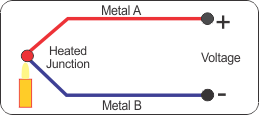
The junction of each type thermocouple produces a specific millivoltage across it at a specific temperature. A thermocouple consists of two junctions connected in opposition.

HOW TO DETERMINE THE MEASURING JUNCTION TEMPERATURE
Example #1 Type “T” Thermocouple
Measured “VD” = 3.41 mV
Reference Junction Temperature = 22°C (71.6°F)
Example #2 Type “T” Thermocouple
Measured “VD” = 4.47 mV
Reference Junction Temperature = -5°C (23°F) (lower than the table reference of 0°C)
Metric/English Scale Conversion °C = °F – 32 °F = 1.8°C + 32
| * P=Positive Leg N = Negative Leg **”Standard” grade wire is sufficiently accurate for most applications. The purity and composition of “premium” grade wire is more closely controlled, and its millivoltage output is closer to the NIST standard chart and therefore reads somewhat more accurately than the “standard” grade does. NOTE: Individual T/C units may be calibrated by measuring their output at several known temperatures and preparing an error correction chart. This chart is used to eliminate any deviation from the “standard” output millivoltage versus temperature readings inherent in this particular thermocouple. The result is known as an “NIST” traceable thermocouple. |
Also Read: Basics 0f 4-20mA Current Signals
Rotating equipment packages such as pumps, compressors, turbines need the lube oil consoles for their…
This article explains how to blink lights in ladder logic with a detailed explanation video…
In this article, a simple example will teach you the conversion from Boolean algebra to…
In this article, you will learn the PLC cooking timer example for kitchen automation using…
Learn an example PLC program to control a pump based on level sensors using ladder…
In the PLC timer application for security camera recording, when motion is detected then camera…
View Comments
A more accurate but more complex way, is to use a real cold junction TC that is inserted in water of 0°C. This is water with melting ice in it. This gives a mV reading that equals the hot junction temperature.
A little remark. Besides the American standard and tables, there are also German standards in use. Do not mix them since the values are different. Make sure which type of TC one is dealing with.
Hi sir
I am katha ramesh i asking about LBD ,card voltage 8 v,but when switch active 4.5v showing ,when switch normal voltage 7.5 v how generat 4.5v and 7.5v in LBD
Please reply.
PT 100 3 wire
calculate Thermocouple Temperature by measuring the output millivoltage
measurement ,errors,working principle
Hi
Why using 3 and 4 wire in RTD ?
What is the usage for this wires ?
In 2 and 3 wire RTD lead resistance added in 4 wire RTD no lead resistance so 4 wire RTD get accurate value