Inst ToolsInst ToolsInst Tools
  • Courses
  • Automation
    • PLC
    • Control System
    • Safety System
    • Communication
    • Fire & Gas System
  • Instrumentation
    • Design
    • Pressure
    • Temperature
    • Flow
    • Level
    • Vibration
    • Analyzer
    • Control Valve
    • Switch
    • Calibration
    • Erection & Commissioning
  • Interview
    • Instrumentation
    • Electrical
    • Electronics
    • Practical
  • Q&A
    • Instrumentation
    • Control System
    • Electrical
    • Electronics
    • Analog Electronics
    • Digital Electronics
    • Power Electronics
    • Microprocessor
  • Request
Search
  • Books
  • Software
  • Projects
  • Process
  • Tools
  • Basics
  • Formula
  • Power Plant
  • Root Cause Analysis
  • Electrical Basics
  • Animation
  • Standards
  • 4-20 mA Course
  • Siemens PLC Course
Reading: Hall Effect Sensor Working Principle Animation
Share
Notification Show More
Font ResizerAa
Inst ToolsInst Tools
Font ResizerAa
  • Courses
  • Design
  • PLC
  • Interview
  • Control System
Search
  • Courses
  • Automation
    • PLC
    • Control System
    • Safety System
    • Communication
    • Fire & Gas System
  • Instrumentation
    • Design
    • Pressure
    • Temperature
    • Flow
    • Level
    • Vibration
    • Analyzer
    • Control Valve
    • Switch
    • Calibration
    • Erection & Commissioning
  • Interview
    • Instrumentation
    • Electrical
    • Electronics
    • Practical
  • Q&A
    • Instrumentation
    • Control System
    • Electrical
    • Electronics
    • Analog Electronics
    • Digital Electronics
    • Power Electronics
    • Microprocessor
  • Request
Follow US
All rights reserved. Reproduction in whole or in part without written permission is prohibited.
Inst Tools > Blog > Animation > Hall Effect Sensor Working Principle Animation

Hall Effect Sensor Working Principle Animation

Last updated: June 6, 2018 5:11 pm
Editorial Staff
Animation How It Works Switches
1 Comment
Share
5 Min Read
SHARE

A Hall effect sensor is a transducer that varies its output voltage in response to a magnetic field. Hall effect sensors are used for proximity switching, positioning, speed detection, and current sensing applications.

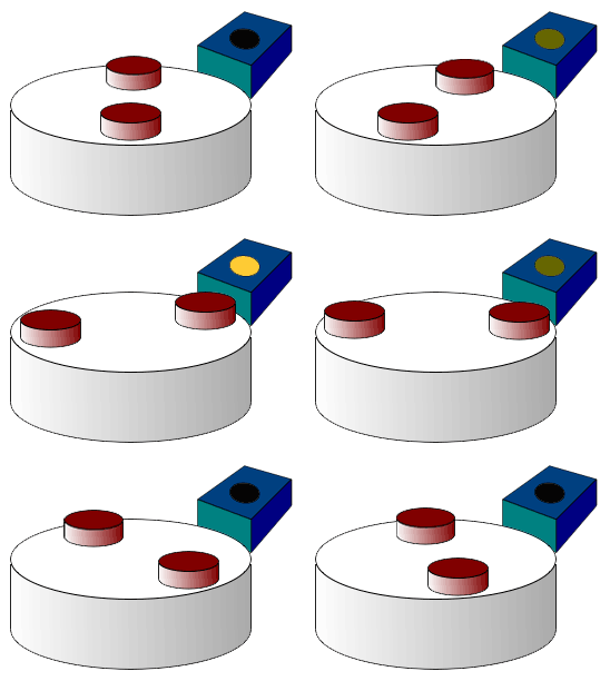
hall-effect-sensor

Fig : A wheel containing two magnets passing by a Hall effect sensor

In its simplest form, the sensor operates as an analog transducer, directly returning a voltage. With a known magnetic field, its distance from the Hall plate can be determined. Using groups of sensors, the relative position of the magnet can be deduced.

Frequently, a Hall sensor is combined with circuitry that allows the device to act in a digital (on/off) mode, and may be called a switch in this configuration.

WORKING PRINCIPLE

A Hall probe contains an indium compound semiconductor crystal such as indium antimonide, mounted on an aluminum backing plate, and encapsulated in the probe head.

When the Hall probe is held so that the magnetic field lines are passing at right angles through the sensor of the probe, the sensor gives a reading of the value of magnetic flux density (B). A current is passed through the crystal which, when placed in a magnetic field has a “Hall effect” voltage developed across it. The Hall effect is seen when a conductor is passed through a uniform magnetic field. The hall effect voltage produced is an indication of magnetic object passed around it. Hence the Hall effect voltage is the signal output and used to sense an object near it.

Also Read: Proximity Switch Animation

ADVANTAGES

A Hall effect sensor may operate as an electronic switch.

  • Such a switch costs less than a mechanical switch and is much more reliable.
  • It can be operated up to 100 kHz.
  • It does not suffer from contact bounce because a solid state switch with hysteresis is used rather than a mechanical contact.
  • It will not be affected by environmental contaminants since the sensor is in a sealed package. Therefore it can be used under severe conditions.

In the case of linear sensor (for the magnetic field strength measurements), a Hall effect sensor:

  • can measure a wide range of magnetic fields
  • is available that can measure either North or South pole magnetic fields
  • can be flat

DISADVANTGAES

Hall effect sensors provide much lower measuring accuracy than fluxgate magnetometers or magnetoresistance-based sensors. Moreover, Hall effect sensors drift significantly, requiring compensation.

APPLICATIONS

Position sensing

Sensing the presence of magnetic objects (connected with the position sensing) is the most common industrial application of Hall effect sensors, especially those operating in the switch mode (on/off mode). The Hall effect sensors are also used in the brushless DC motor to sense the position of the rotor and to switch the transistors in the right sequence.

Smartphones use hall sensors to determine if the Flip Cover accessory is closed.

DC current transformers

Hall effect sensors may be utilized for contactless measurements of DC current in current transformers. In such a case the Hall effect sensor is mounted in the gap in magnetic core around the current conductor. As a result, the DC magnetic flux can be measured, and the DC current in the conductor can be calculated. The Hall effect was used to detect DC current in a superconducting DC transformer also.

Automotive fuel level indicator

The Hall sensor is used in some automotive fuel level indicators. The main principle of operation of such indicator is position sensing of a floating element. This can either be done by using a vertical float magnet or a rotating lever sensor.

  • In a vertical float system a permanent magnet is mounted on the surface of a floating object. The current carrying conductor is fixed on the top of the tank lining up with the magnet. When the level of fuel rises, an increasing magnetic field is applied on the current resulting in higher Hall voltage. As the fuel level decreases, the Hall voltage will also decrease. The fuel level is indicated and displayed by proper signal condition of Hall voltage.
  • In a rotating lever sensor a diametrically magnetized ring magnet rotates about a linear hall sensor. The sensor only measures the perpendicular (vertical) component of the field. The strength of the field measured correlates directly to the angle of the lever and thus the level of the fuel tank.
Don't Miss Our Updates
Be the first to get exclusive content straight to your email.
We promise not to spam you. You can unsubscribe at any time.
Invalid email address
You've successfully subscribed !

Continue Reading

Thermistor Working Principle
Level Indicators Working Principle
Limit Switch Animation
Bellows Pressure Sensors Working Principle Animation
Basic Working Principle of Vortex Flowmeter
Tuning Fork Level Switch Principle
Share This Article
Facebook Whatsapp Whatsapp LinkedIn Copy Link
Share
1 Comment
  • G L Pande says:
    February 14, 2023 at 12:40 am

    I think that hall effect sensor can used as a string based musical instruments .we can get audio signal(ac) by hall effect output

    Reply

Leave a Reply Cancel reply

Your email address will not be published. Required fields are marked *

Stay Connected

128.3kFollowersLike
69.1kFollowersFollow
210kSubscribersSubscribe
38kFollowersFollow

Categories

Explore More

Pushbutton switches and Types of Switches
Thermocouple Working Principle
PLC Sinking and Sourcing Explanation
Oval Gear Meter – Principle, Advantages, Limitations, Applications
Electromagnetic Flow Meters Working Principle
Capacitance Level Measurement Working Principle
Reed switch Working Principle
Zero Speed Switch Working Principle

Keep Learning

Pull Cord Switch Principle

Pull Cord Switch Working Principle

Radiometric level Principle

Radiometric level measurement Working Principle

Switch Contact checking with oscilloscope

What is Contact bounce ?

Swirl Flowmeters Principle

Swirl Flow Meters Working Principle

magnetic-level-gauge-principle

Magnetic Level Gauge Working Principle Animation

CO2 Analzer Working Principle

Infrared Non Dispersive CO2 Analyzer Working Principle

Argonite/CO2 Flooding System Master & Slave Cylinder Operation

MOS Gas Sensor Principle

MOS Type Gas Sensor Principle

Learn More

Industrial Automation Components

Industrial Automation Components Questions and Answers

Siemens Profibus Interface DP

How to Create New Project Using Simatic Manager

Direct Lift Diaphragm Normally Open Solenoid Valve

Direct Lift Diaphragm Solenoid Valve Principle

Steam Turbine Driven Centrifugal Compressors Leak due to Broken Instrument

Steam Turbine Driven Centrifugal Compressors Leak due to Broken Instrument

What is calibration?

Conductive Level Measurement Working Principle

Conductive Level Measurement Working Principle

What can you do with an Engineering Degree

What Can You Do with an Engineering Degree?

Control Valve with Positioner

 Control Valve Accessories – Principle, Purpose, Advantages

Menu

  • About
  • Privacy Policy
  • Copyright

Quick Links

  • Learn PLC
  • Helping Hand
  • Part Time Job

YouTube Subscribe

Follow US
All rights reserved. Reproduction in whole or in part without written permission is prohibited.
Welcome Back!

Sign in to your account

Username or Email Address
Password

Lost your password?