Inst ToolsInst ToolsInst Tools
  • Courses
  • Automation
    • PLC
    • Control System
    • Safety System
    • Communication
    • Fire & Gas System
  • Instrumentation
    • Design
    • Pressure
    • Temperature
    • Flow
    • Level
    • Vibration
    • Analyzer
    • Control Valve
    • Switch
    • Calibration
    • Erection & Commissioning
  • Interview
    • Instrumentation
    • Electrical
    • Electronics
    • Practical
  • Q&A
    • Instrumentation
    • Control System
    • Electrical
    • Electronics
    • Analog Electronics
    • Digital Electronics
    • Power Electronics
    • Microprocessor
  • Request
Search
  • Books
  • Software
  • Projects
  • Process
  • Tools
  • Basics
  • Formula
  • Power Plant
  • Root Cause Analysis
  • Electrical Basics
  • Animation
  • Standards
  • 4-20 mA Course
  • Siemens PLC Course
Reading: Fieldbus Cables
Share
Font ResizerAa
Inst ToolsInst Tools
Font ResizerAa
  • Courses
  • Design
  • PLC
  • Interview
  • Control System
Search
  • Courses
  • Automation
    • PLC
    • Control System
    • Safety System
    • Communication
    • Fire & Gas System
  • Instrumentation
    • Design
    • Pressure
    • Temperature
    • Flow
    • Level
    • Vibration
    • Analyzer
    • Control Valve
    • Switch
    • Calibration
    • Erection & Commissioning
  • Interview
    • Instrumentation
    • Electrical
    • Electronics
    • Practical
  • Q&A
    • Instrumentation
    • Control System
    • Electrical
    • Electronics
    • Analog Electronics
    • Digital Electronics
    • Power Electronics
    • Microprocessor
  • Request
Follow US
All rights reserved. Reproduction in whole or in part without written permission is prohibited.
Inst Tools > Blog > Communication > Fieldbus Cables

Fieldbus Cables

Last updated: January 26, 2019 12:59 pm
Editorial Staff
Communication
No Comments
Share
2 Min Read
SHARE

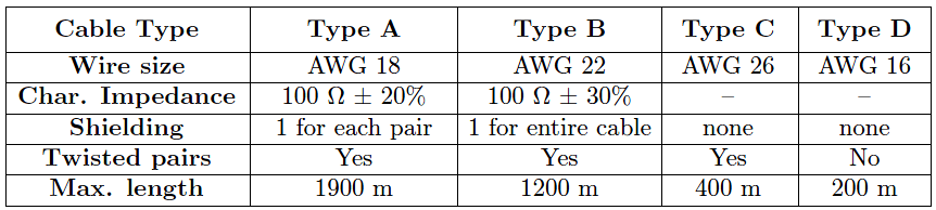
Fieldbus cable is rated according to a four-level code (A, B, C, or D), each successive letter representing a cable of lower quality6. The following table gives minimum specifications for each FF cable type:

fieldbus cables

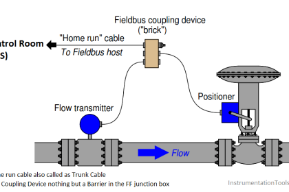
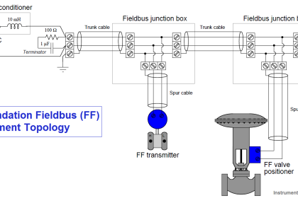
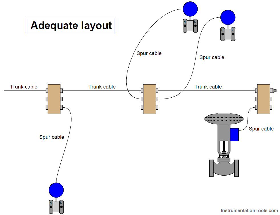
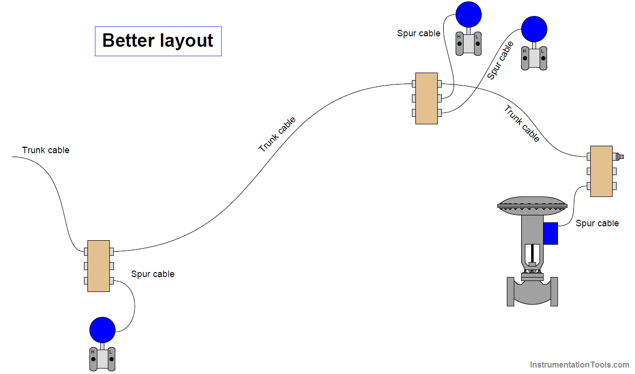
Bear in mind that the maximum length given for each cable type is the total length of all cables in a segment, trunk length plus all spur lengths. As a general rule, spur lengths should be kept as short as possible. It is better to route the trunk cable in a serpentine fashion to locate coupling devices close to their respective instruments than it is to streamline the trunk cable routing. The following illustrations contrast the two approaches:

fieldbus cables layout

fieldbus cables route layout

If greater lengths are required for a network segment, devices known as repeaters may be added which sense and re-broadcast the Manchester-encoded FF signal between trunk cables. A maximum of four repeaters may be used to extend any H1 segment.

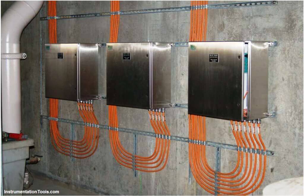
As always, neat wiring practices help make an instrument system easier to maintain and to diagnose when things go wrong. The following photograph shows a triad of FOUNDATION Fieldbus junction boxes and (orange) network cables. Coupling devices located inside each enclosure link each spur cable to the trunk:

FOUNDATION Fieldbus junction boxes

Don't Miss Our Updates
Be the first to get exclusive content straight to your email.
We promise not to spam you. You can unsubscribe at any time.
Invalid email address
You've successfully subscribed !

Continue Reading

Foundation Fieldbus Communication Management
History of OPC Protocol
Difference between TCP/IP Model and OSI Model
Foundation Fieldbus Segment Design
Difference Between Modbus TCP IP and Profinet
Fieldbus Transmitters Calibration and Ranging
Share This Article
Facebook Whatsapp Whatsapp LinkedIn Copy Link
Share
Leave a Comment

Leave a Reply Cancel reply

Your email address will not be published. Required fields are marked *

Stay Connected

128.3kFollowersLike
69.1kFollowersFollow
210kSubscribersSubscribe
38kFollowersFollow

Categories

Explore More

Modbus Communication Interview Questions and Answers
Foundation Fieldbus Signal Conversion Formula
Serial Communication Data Transmission Modes
Comparison between Foundation Fieldbus and Profibus
What is OPC ?
HART Communication Tutorial Part 2
What is a Network Connector? – Types of Connectors
Purpose of Gateways, Bridges & Routers in Networking

Keep Learning

Foundation Fieldbus Tutorials

Foundation Fieldbus Tutorials

Surge Protection for the Fieldbus System

Tree (chicken foot) topology

Fieldbus Device Capability

Fieldbus Control

Fieldbus Control

HART Communication Problems

HART Communication Problems

Optical Fiber Size

Fiber Optic Cable Connectors, Routing, and Safety

HART Transmitter Calibration

How are HART instruments Calibrated?

Dissolved oxygen measurement using Optical Fiber Communication

Fiber Optic Sensors

Learn More

ATEX Ratings, Intrinsic Safety, Hazardous Areas and Explosive Atmospheres

ATEX Ratings, Intrinsic Safety, Hazardous Areas and Explosive Atmospheres

Procedure for the Repair of Control Valve

Basic Steps and Procedure for the Repair of Control Valve

Difference between PLC and Computers

Difference between PLC and Computers

Gas Detection Definitions

Standard Gas Detection Definitions

Electrical Machines Questions and Answers

Permanent Magnet DC Motor (PMDC) Questions

Difference Between AA and AAA Batteries

Difference Between AA and AAA Batteries

PLC Program for Solenoid, Pilot Lamp, and Switch with Alarm

PLC Program for Solenoid, Pilot Lamp, and Switch with Alarm

FDA Process Validation

Why You Need FDA Process Validation and How to Do It Right ?

Menu

  • About
  • Privacy Policy
  • Copyright

Quick Links

  • Learn PLC
  • Helping Hand
  • Part Time Job

YouTube Subscribe

Follow US
All rights reserved. Reproduction in whole or in part without written permission is prohibited.
Welcome Back!

Sign in to your account

Username or Email Address
Password

Lost your password?