Inst ToolsInst ToolsInst Tools
  • Courses
  • Automation
    • PLC
    • Control System
    • Safety System
    • Communication
    • Fire & Gas System
  • Instrumentation
    • Design
    • Pressure
    • Temperature
    • Flow
    • Level
    • Vibration
    • Analyzer
    • Control Valve
    • Switch
    • Calibration
    • Erection & Commissioning
  • Interview
    • Instrumentation
    • Electrical
    • Electronics
    • Practical
  • Q&A
    • Instrumentation
    • Control System
    • Electrical
    • Electronics
    • Analog Electronics
    • Digital Electronics
    • Power Electronics
    • Microprocessor
  • Request
Search
  • Books
  • Software
  • Projects
  • Process
  • Tools
  • Basics
  • Formula
  • Power Plant
  • Root Cause Analysis
  • Electrical Basics
  • Animation
  • Standards
  • 4-20 mA Course
  • Siemens PLC Course
Reading: Electrical Actuators
Share
Font ResizerAa
Inst ToolsInst Tools
Font ResizerAa
  • Courses
  • Design
  • PLC
  • Interview
  • Control System
Search
  • Courses
  • Automation
    • PLC
    • Control System
    • Safety System
    • Communication
    • Fire & Gas System
  • Instrumentation
    • Design
    • Pressure
    • Temperature
    • Flow
    • Level
    • Vibration
    • Analyzer
    • Control Valve
    • Switch
    • Calibration
    • Erection & Commissioning
  • Interview
    • Instrumentation
    • Electrical
    • Electronics
    • Practical
  • Q&A
    • Instrumentation
    • Control System
    • Electrical
    • Electronics
    • Analog Electronics
    • Digital Electronics
    • Power Electronics
    • Microprocessor
  • Request
Follow US
All rights reserved. Reproduction in whole or in part without written permission is prohibited.
Inst Tools > Blog > Control Valves > Electrical Actuators

Electrical Actuators

Last updated: March 21, 2019 4:24 pm
Editorial Staff
Control Valves
No Comments
Share
6 Min Read
SHARE

Electric motors have long been used to actuate large valves, especially valves operated as on/off (“shutoff”) devices.

Advances in motor design and motor control circuitry have brought motor operated valve (MOV) technology to the point where it now competes with legacy actuator technologies such as pneumatic in actuating throttling valves as well.
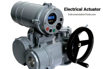
Electrical Actuator

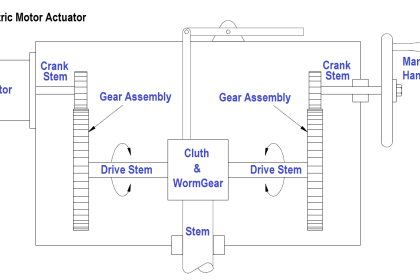
Most electric valve actuators use a worm gear set to reduce the high rotational speed of the electric motor to a slow rotation suitable for moving a large valve mechanism.

An illustration of a worm gear set appears here:

Worm gear mechanism

The worm screw looks much like a threaded fastener, with its “threads” properly pitched to engage with the teeth of the worm wheel gear.

As the worm screw turns, it slowly pushes or pulls the circumference of the worm wheel, resulting in a large gear ratio (i.e. many turns of the screw are required to produce a single turn of the wheel).

This slow-turning wheel may then be used to move a sliding-stem valve by means of a threaded shaft (another screw) or used to directly turn a rotary valve (e.g. butterfly, ball, plug).

Also Read : Motor Trip Logic using PLC

An electric actuator appears in the next photograph, providing on/off rotary actuation to a ball valve. This particular electric actuator comes with a hand crank for manual operation, in the event that the electric motor (or the power provided to it) fails:

motor operated valve (MOV) principle

A small lever to the left of the hand crank actuates a clutch mechanism to engage or disengage the valve mechanism from the electric motor and the hand wheel.

This clutch “selects” either the motor or the hand wheel as the prime mover for the valve, to avoid having the hand wheel spin as the motor turns. Unless this lever is first moved to the “manual” position, turning the hand wheel accomplishes nothing.

The next photograph shows an electric valve actuator coupled to a large butterfly valve.

Although nothing visible in this photograph betrays the nature of this actuator’s signaling, it happens to be digital rather than analog, receiving position commands through a Profibus digital network rather than an analog 4-20 mA current signal:

Electrical Actuator Valve

The shape of the actuator’s metal casing reveals the final gear drive of this actuator as a worm gear set. Note the round shape of the casing where the open/close indicator is located (at the centerline of the butterfly valve stem): this contains the worm wheel.

Note immediately to the left of that round casing is a vertically-oriented cylinder shape: this contains the worm screw, which engages with the teeth of the worm wheel.

Above the worm screw is a parallel-shaft spur gear set which acts to further reduce the speed of the actuator’s electric motor: the motor shaft terminates in a small gear, which meshes with a larger gear that turns the worm screw shaft.

Above the parallel shaft gear set is the main casing of the actuator, which actually contains its own internal worm gear set. This multiple-stage gear reduction means that the motor spins very fast in comparison to the butterfly element inside the valve, and that the butterfly is capable of exerting a fantastic amount of torque in comparison to the torque rating of the electric motor.

Electric motors require no external fluid power system to function, unlike pneumatic or hydraulic actuators. All they require is a source of electrical power (often 480 volts AC, three-phase).

Some electric valve actuators even have the capability of operating from the power of an electric battery pack, for reliable operation in the event of a power system outage.

Virtually all electric valve actuators require some form of feedback to indicate the valve’s position.

At minimum, this consists of limit switches to indicate when the valve is fully shut and fully open. For throttling services, an electric actuator requires an actual valve position sensor so that it may precisely adjust the valve to any desired state. This sensor may take the form of a potentiometer, or a variable differential transformer (LVDT or RVDT), or pulse encoder.

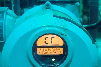
This Rotork brand MOV has a digital display at one end showing its closed status both in text (“Closed Limit”) and symbolically (by the vertical line, which is supposed to represent a closed butterfly element):

Motor Local Control Panel

In addition to visual indicators of status, electric valve actuators commonly provide auxiliary electrical contacts signaling fully-open and fully-closed positions, which may be used to energize remote indicator lights or discrete input channels of control systems (e.g. PLC).

Throttling-service MOVs also provide analog (and/or digital) signaling of valve stem position for remote indication or feedback to an electronic control system.

Also Read : Dome Valve Principle

Don't Miss Our Updates
Be the first to get exclusive content straight to your email.
We promise not to spam you. You can unsubscribe at any time.
Invalid email address
You've successfully subscribed !

Continue Reading

Basic Requirements of Control Valves Sizing
What is a Electric Motor Actuator ?
Solenoid Valve Failure in Plant Start-Up: Identifying the Root Cause
What is Needle Valve ?
How-to do Control Valve Calibration?
What is a Float Control Valve? Types, Advantages, Disadvantages
Share This Article
Facebook Whatsapp Whatsapp LinkedIn Copy Link
Share
Leave a Comment

Leave a Reply Cancel reply

Your email address will not be published. Required fields are marked *

Stay Connected

128.3kFollowersLike
69.1kFollowersFollow
210kSubscribersSubscribe
38kFollowersFollow

Categories

Explore More

Control Valve Characteristics
Pneumatic Piping Design and Specification
Gas Valve Sizing
Malfunctioning Inlet Check Valves caused chaos at Compressor stop/trip
Direct Lift Diaphragm Solenoid Valve Principle
Complementary Control Valve Sequence
Control Valve Selection Guide
Control Valve Testing for Noise Measurement

Keep Learning

Speed of Power Actuators

Speed of Actuators

Basic Configuration of Motor Operated Valve

Rotork Motor Operated Valve Basic Configuration

valve plug and seat damage

Control Valve Erosion Problems

Valve Pneumatic Actuator

What is a Pneumatic Actuator ?

Incident Investigation: Motor Operated Valve Lesson

Incident Investigation: Motor Operated Valve Lesson

Why Restriction Orifice is some distance from Blowdown valve

Why Restriction Orifice is some distance from Blowdown valve ?

Tilting Disk Check Valve Principle

What is Tilting Disk Check Valve ?

Stop Check valve

What is Stop Check valve ?

Learn More

Computer Networks Multiple Choice Questions

150 Computer Networks Multiple Choice Questions and Answers

Boolean Algebra to PLC Logic

From Boolean Algebra to PLC Logic

Comparison of Temperature Sensors - Industrial Process Control

Comparison of Temperature Sensors – Industrial Process Control

electrical-drives-questions-answers

Electrical Drives Questions & Answers

Fire Detectors Working Principle

Basics of Fire Detection and Alarm System

PLC Programming Best Practices and Tips

PLC Programming Best Practices and Tips

Laminar Flow Meter Working Principle

Laminar Flow Meter Working Principle

Furnace Draft Control System

Furnace Draft Control System

Menu

  • About
  • Privacy Policy
  • Copyright

Quick Links

  • Learn PLC
  • Helping Hand
  • Part Time Job

YouTube Subscribe

Follow US
All rights reserved. Reproduction in whole or in part without written permission is prohibited.
Welcome Back!

Sign in to your account

Username or Email Address
Password

Lost your password?