Inst ToolsInst ToolsInst Tools
  • Courses
  • Automation
    • PLC
    • Control System
    • Safety System
    • Communication
    • Fire & Gas System
  • Instrumentation
    • Design
    • Pressure
    • Temperature
    • Flow
    • Level
    • Vibration
    • Analyzer
    • Control Valve
    • Switch
    • Calibration
    • Erection & Commissioning
  • Interview
    • Instrumentation
    • Electrical
    • Electronics
    • Practical
  • Q&A
    • Instrumentation
    • Control System
    • Electrical
    • Electronics
    • Analog Electronics
    • Digital Electronics
    • Power Electronics
    • Microprocessor
  • Request
Search
  • Books
  • Software
  • Projects
  • Process
  • Tools
  • Basics
  • Formula
  • Power Plant
  • Root Cause Analysis
  • Electrical Basics
  • Animation
  • Standards
  • 4-20 mA Course
  • Siemens PLC Course
Reading: Draw Limit Switch Symbol ?
Share
Font ResizerAa
Inst ToolsInst Tools
Font ResizerAa
  • Courses
  • Design
  • PLC
  • Interview
  • Control System
Search
  • Courses
  • Automation
    • PLC
    • Control System
    • Safety System
    • Communication
    • Fire & Gas System
  • Instrumentation
    • Design
    • Pressure
    • Temperature
    • Flow
    • Level
    • Vibration
    • Analyzer
    • Control Valve
    • Switch
    • Calibration
    • Erection & Commissioning
  • Interview
    • Instrumentation
    • Electrical
    • Electronics
    • Practical
  • Q&A
    • Instrumentation
    • Control System
    • Electrical
    • Electronics
    • Analog Electronics
    • Digital Electronics
    • Power Electronics
    • Microprocessor
  • Request
Follow US
All rights reserved. Reproduction in whole or in part without written permission is prohibited.
Inst Tools > Blog > Practical Questions > Draw Limit Switch Symbol ?

Draw Limit Switch Symbol ?

Last updated: June 6, 2018 9:56 am
Editorial Staff
Practical Questions
No Comments
Share
1 Min Read
SHARE

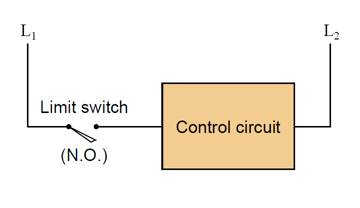
Limit switches are often used on the doors of electrical enclosures and cabinets to automatically shut off power or shut down a machine’s function if anyone opens the door for maintenance purposes. The limit switch is typically mounted in such a way that a shut door holds the switch lever in the “actuated” position. When the door opens wide, the limit switch lever is released and the switch returns to its “normal” status.

Draw the appropriate limit switch symbol in this ladder logic diagram so that the control circuit (shown as a rectangular box) gets shut down if ever someone opens the cabinet door:

Limit switches Questions

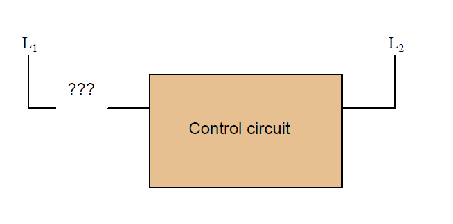
Be sure to denote whether this limit switch needs to be normally-open (N.O.) or normally-closed (N.C.).

Answer :

Limit Switches Wiring

Share Your Answer / Comments

Credits : by Tony R. Kuphaldt – under CC BY 1.0

Don't Miss Our Updates
Be the first to get exclusive content straight to your email.
We promise not to spam you. You can unsubscribe at any time.
Invalid email address
You've successfully subscribed !

Continue Reading

Determine the Pressure at Each Port of DP Transmitter
Calculate PSV Lift Pressure
How Manometer Measures Differential Pressure for Different Fluids?
A Question on Density Gauge
Practical Process Control System Questions & Answers – 8
Resistance Temperature Detector (RTD) Questions – 1
Share This Article
Facebook Whatsapp Whatsapp LinkedIn Copy Link
Share
Leave a Comment

Leave a Reply Cancel reply

Your email address will not be published. Required fields are marked *

Stay Connected

128.3kFollowersLike
69.1kFollowersFollow
210kSubscribersSubscribe
38kFollowersFollow

Categories

Explore More

Pneumatic Level Transmitter Value Struck?
Liquid Level Measurement using Pressure Transmitter Questions
Displacer Type Density Transmitter Question
Overhead Product Pressure Control Loop
How much Pressure is applied to Inclined Water Manometer?
Pneumatic Level Transmitter Calibration Table
Displacer Level Transmitter Question & Answer
Purpose of Stop in a Pressure Measuring Instrument

Keep Learning

surface-mounted water pump

Surface-mounted Water Pump

two chemical streams are mixed together

Practical Process Control System Questions & Answers – 12

Question on Remote Seal with Capillary Tubing Transmitter

Question on Remote Seal with Capillary Tubing Transmitter

Siemens PLC Block Diagram

Programmable Logic Controller (PLC) Questions and Answers – 14

liquid flow control system

Practical Process Control System Questions & Answers – 7

compressor emergency shutdown system

Solenoid Valves Questions & Answers – 2

Programmable Logic Controller (PLC) Questions and Answers

Programmable Logic Controller (PLC) Questions and Answers – 1

Loop Diagram

PT Loop Diagram Faults

Learn More

butt weld end Plug Valves Leaks Stopped

PTFE lined 6” 300# butt weld end Plug Valves Leaks Stopped Forever

What is a K Factor

Flow Meter K-factor and Calculations

Electrical Machines Questions and Answers

Electrical Machines Loss Dissipation Quiz

Compressor IP Case Discharge Temperature Gradually Increases

Compressor IP Case Discharge Temperature Gradually Increases

Spiral bimetallic thermometer principle

Spiral Bimetallic Thermometer Principle

Learn PLC in Hindi

Learn PLC in Hindi

PLC Motor Control Circuit

Motor Trip Logic using PLC Programming

Control Valve Flow Characteristics

Different Control Valve Flow Characteristics

Menu

  • About
  • Privacy Policy
  • Copyright

Quick Links

  • Learn PLC
  • Helping Hand
  • Part Time Job

YouTube Subscribe

Follow US
All rights reserved. Reproduction in whole or in part without written permission is prohibited.
Welcome Back!

Sign in to your account

Username or Email Address
Password

Lost your password?