Inst ToolsInst ToolsInst Tools
  • Courses
  • Automation
    • PLC
    • Control System
    • Safety System
    • Communication
    • Fire & Gas System
  • Instrumentation
    • Design
    • Pressure
    • Temperature
    • Flow
    • Level
    • Vibration
    • Analyzer
    • Control Valve
    • Switch
    • Calibration
    • Erection & Commissioning
  • Interview
    • Instrumentation
    • Electrical
    • Electronics
    • Practical
  • Q&A
    • Instrumentation
    • Control System
    • Electrical
    • Electronics
    • Analog Electronics
    • Digital Electronics
    • Power Electronics
    • Microprocessor
  • Request
Search
  • Books
  • Software
  • Projects
  • Process
  • Tools
  • Basics
  • Formula
  • Power Plant
  • Root Cause Analysis
  • Electrical Basics
  • Animation
  • Standards
  • 4-20 mA Course
  • Siemens PLC Course
Reading: Dissolved oxygen probe calibration procedure
Share
Notification Show More
Font ResizerAa
Inst ToolsInst Tools
Font ResizerAa
  • Courses
  • Design
  • PLC
  • Interview
  • Control System
Search
  • Courses
  • Automation
    • PLC
    • Control System
    • Safety System
    • Communication
    • Fire & Gas System
  • Instrumentation
    • Design
    • Pressure
    • Temperature
    • Flow
    • Level
    • Vibration
    • Analyzer
    • Control Valve
    • Switch
    • Calibration
    • Erection & Commissioning
  • Interview
    • Instrumentation
    • Electrical
    • Electronics
    • Practical
  • Q&A
    • Instrumentation
    • Control System
    • Electrical
    • Electronics
    • Analog Electronics
    • Digital Electronics
    • Power Electronics
    • Microprocessor
  • Request
Follow US
All rights reserved. Reproduction in whole or in part without written permission is prohibited.
Inst Tools > Blog > Analyzers > Dissolved oxygen probe calibration procedure

Dissolved oxygen probe calibration procedure

Last updated: September 14, 2016 11:03 pm
Editorial Staff
Analyzers Calibration
No Comments
Share
6 Min Read
SHARE

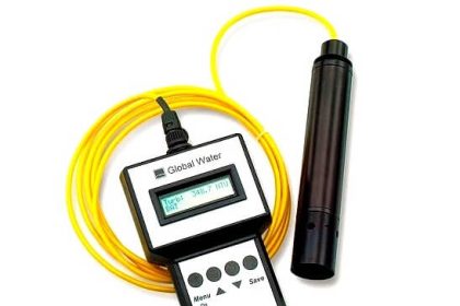
Dissolved oxygen (DO) content in water is measured using a membrane electrode. To insure proper operation, the DO probe’s membrane and electrolyte should be replaced prior to calibration for the sampling event. The new membrane may need to be conditioned before it is used; consult manufacturer’s manual on how the conditioning is to be performed. Failure to perform this step may lead to erratic measurements. Before performing the calibration/measurements, inspect the membrane for air bubbles and nicks.

Calibration Procedure:

1. Gently dry the temperature sensor and remove any water droplets from the DO probe’s sensor membrane according to manufacturer’s instructions; Note that the evaporation of moisture on the temperature sensor or DO probe may influence the readings during calibration.

2. Create a 100 percent water-saturated air environment by placing a wet sponge or a wet paper towel on the bottom of the DO calibration container. Place the DO probe into the calibration container. The probe is loosely fitted into the calibration container to prevent the escape of moisture evaporating from the sponge or paper towel while maintaining ambient pressure (see manufacturer’s instructions). Note that the probe and the temperature sensor must not come in contact with these wet items.

3. Allow the confined air to become saturated with water vapor (saturation occurs in approximately 10 to 15 minutes). During this time, tum on the instrument to allow the DO probe to warm-up. Select the measurement mode. Check the temperature readings. Readings must stabilize before continuing to the next step.

4. Select calibration mode; then select “DO %”.

5. Enter the local barometric pressure (usually in mm of mercury) for the sampling location into the instrument. This measurement must be determined from an on-site barometer. Do not use barometric pressure obtained from the local weather services unless the pressure is corrected for the elevation ofthe sampling location. [Note: inches of mercury times 25.4 mmlinch equals mm of mercury or consult Oxygen Solubility at Indicated Pressure chart attached to the SOP for conversion at selected .pressures]

6. The instrument should indicate that the calibration is in progress. After calibration, the instrument should display percent saturated DO.

7. Select measurement mode and set the display to read DO mg!L and temperature. Compare the DO mg/L reading to the Oxygen Solubility at Indicated Pressure chart attached to the SOP. The numbers should agree. If they do not agree within the accuracy of the instrument (usually ± 0.2 mg!L), repeat calibration. If this does not work, change the membrane and electrolyte solution.

8. Remove the probe from the container and place it into a 0.0 mg/L DO solution (see footnote). Check temperature readings. They must stabilize before continuing.

9. Wait until the “mg/L DO” readings have stabilized. Theinstrument should read less than 0.5 mg/L (assuming an accuracy of ± 0.2 mglL). If the instrument reads above 0.5 mg/L or reads negative, it will be necessary to clean the probe, and change the membrane and electrolyte solution. If this does not work, try a new 0.0 mg/L DO solution. If these changes do not work, contact the manufacturer. Note: some projects and instruments may have different accuracy requirements. The 0.5 mg/L value may need to be adjusted based on the accuracy requirements of the project or instrument.

10. After the calibration has been completed, rinse the probe with tap or deionized water and store the probe according to manufacturer’s instructions. It is important that all of the 0.0 mg/L DO solution be rinsed off the probe so as not to effect the measurement of environmental samples.

11. Record calibration information on calibration log sheet.

Note:

1. You can either purchase the 0.0 mg/L DO solution from a vendor or prepare the solution yourself. To prepare a 0.0 mg/L DO solution, follow the procedure stated in Standard Methods (Method 4500-0 G). The method basically states to add excess sodium sulfite (until no more dissolves) and a trace amount of cobalt chloride (read warning on the label before use) to water. This solution is prepared prior to the sampling event. Note: this solution can be made without cobalt chloride, but the probe will take longer to respond to the low DO concentration.

2. some manufacturers require an altitude correction instead of a barometric correction. In that case, enter the altitude correction according to the manufacturer’s directions in Step 5 and then proceed to Step 6.

3. some instruments have a built-in barometer. Follow the manufacturer’s instructions for entering the barometric value in step 5.
Don't Miss Our Updates
Be the first to get exclusive content straight to your email.
We promise not to spam you. You can unsubscribe at any time.
Invalid email address
You've successfully subscribed !

Continue Reading

Important Terms in Calibration
Calibration and Preventative Maintenance Procedures
How to Calibrate the Eddy Current Conductivity Meter?
Functional Testing of Control Valve Positioners
Moisture and Dew Point Analyzer Problems and Troubleshooting Tips
Calibration of Displacer Level Transmitter
Share This Article
Facebook Whatsapp Whatsapp LinkedIn Copy Link
Share
Leave a Comment

Leave a Reply Cancel reply

Your email address will not be published. Required fields are marked *

Stay Connected

128.3kFollowersLike
69.1kFollowersFollow
210kSubscribersSubscribe
38kFollowersFollow

Categories

Explore More

Multiphase Flow Meter Calibration Procedure
Thermocouple Calibration
What is a Dry Block? – Parts of the Temperature Calibrator
Basics of ORP Measurement
Pressure Safety Valve Leak Test Procedure (PSV Testing)
Kiln Inlet Gas Analyzer
Working Principle of Gas chromatograph
Ammonia Gas Detector Working Principle and Calibration

Keep Learning

Multiple Position Calibration of Temperature Chamber (Mapping)

Multiple Position Calibration of Temperature Chamber

process chemical analyzer calibration

Automated Calibration

Pressure Gauge Functional Testing

Pressure Gauge Functional Testing

Strain gage load cells

Load Cell Healthiness Checks

Selection of Weighing Balance

Selection of Weighing Balance and Weight for Calibration

HART Transmitter Calibration

How are HART instruments Calibrated?

Turbidity Analyzer Working Principle

Turbidity Analyzer Working Principle

Pressure Transmitter Calibration Procedure

Pressure Transmitter Calibration Procedure

Learn More

Digital Electronics Objective Questions

Digital Electronics Objective Questions

Smart DP transmitter Formula

Smart DP Transmitter Flow Meter Calculations

Why do we need to Control the Motion using VFD drives

Why do we need to Control the Motion using VFD drives?

Switches, Repeaters, Bridges, Routers, Firewalls

Switches, Repeaters, Bridges, Routers, Firewalls

Sorting PLC Program Simulation

Sorting & Distribution Line PLC Programming – Advanced Logic

Industrial PLC Communication Network

Basics of Industrial Communication Networks

safety control system

Safety Instrumented Burner Management System

Pressure Detection Circuit

Pressure Detection Circuit

Menu

  • About
  • Privacy Policy
  • Copyright

Quick Links

  • Learn PLC
  • Helping Hand
  • Part Time Job

YouTube Subscribe

Follow US
All rights reserved. Reproduction in whole or in part without written permission is prohibited.
Welcome Back!

Sign in to your account

Username or Email Address
Password

Lost your password?