Directional control valves perform only three functions:
- stop fluid flow
- allow fluid flow, and
- change direction of fluid flow.
These three functions usually operate in combination.
Classification of Directional Control Valves
Directional control valves can be classified according to-
- number of ports
- number of positions
- actuating methods
- type of spool.
Example: A 5/2 directional control valve would have five ports and two spool positions.
Number of Ports
Ports that will be counted shall be external ports only. 5/2
Number of Positions
Including the normal and working positions which a valve spool can take there are types like two position, three position and proportional valve …
Actuating Methods
Manual, spring, electrical, pneumatic, and hydraulic.
Manually Operated
Manually operated valves work with simple levers or paddles where the operator applies force to operate the valve. Spring force is sometimes used to recover the position of valve.
Some manual valves utilize either a lever or an external pneumatic or hydraulic signal to return the spool.
Mechanically Operated
Mechanically operated valves apply forces by using cams, wheels, rollers, etc., hence these valves are subjected to wear.
Hydraulically Operated
A hydraulically operated DCV works at much higher pressures than its pneumatic equivalent. They must therefore be far more robust in nature so are precision machined from higher quality and strength materials.
Solenoid Operated
They are widely used in the hydraulics industry. These valves make use of electromechanical solenoids for sliding of the spool. Because simple application of electrical power provides control, these valves are used extensively.
However, electrical solenoids cannot generate large forces unless supplied with large amounts of electrical power. Heat generation poses a threat to extended use of these valves when energized over time. Many have a limited duty cycle. This makes their direct acting use commonly limited to low actuating forces.
Often a low power solenoid valve is used to operate a small hydraulic valve (called the pilot) that starts a flow of fluid that drives a larger hydraulic valve that requires more force.
A bi-stable pneumatic valve is typically a pilot valve that is a 3 ported 2 position detented valve. The valve retains its position during loss of power, hence the bi-stable name.
Bi-stability can be accomplished with a mechanical detent and 2 opposing solenoids or a “magna-latch” magnetic latch with a polarity sensitive coil. Positive opens and negative closes or vice versa. The coil is held in position magnetically when actuated.
Type of Spool
Spool is of two types namely sliding and rotary. Sliding spool is cylindrical in cross section, and the lands and grooves are also cylindrical. Rotary valves have sphere-like lands and grooves in the form of holes drilled through them.
Directional Control Valve
The simplest directional control valve is the 2-way valve. A 2-way valve stops flow or allows flow. A water faucet is a good example of a 2-way valve. A water faucet allows flow or stops flow by manual control.
A single-acting cylinder needs supply to and exhaust from its port to operate. This requires a 3-way valve. A 3-way valve allows fluid flow to an actuator in one position and exhausts the fluid from it in the other position. Some 3-way valves have a third position that blocks flow at all ports.
A double-acting actuator requires a 4-way valve. A 4-way valve pressurizes and exhausts two ports interdependently. A 3-position, 4-way valve stops an actuator or allows it to float. The 4-way function is a common type of directional control valve for both air and hydraulic circuits. A 3-position, 4-way valve is more common in hydraulic circuits.
The 5-way valve is found most frequently in air circuits. A 5-way valve performs the same function as a 4-way valve. The only difference is an extra tank or exhaust port. (Some suppliers call their 5-way valves, “5-ported 4-ways.”)
All spool valves are five ported, but hydraulic valves have internally connected exhaust ports going to a common outlet. Because oil must return to tank, it is convenient to connect the dual tank ports to a single return port.
For air valves, atmosphere is the tank, so exhaust piping is usually unimportant. Using two exhaust ports makes the valve smaller and less expensive. As will be explained later, dual exhausts used for speed-control mufflers or as dual-pressure inlets make this configuration versatile.
Following are schematic symbols for commonly used directional control valves.
2-way directional control valves
A 2-way directional valve has two ports normally called inlet and outlet. When the inlet is blocked in the at-rest condition, as shown in Figure 8-1, it is referred to as “normally closed” (NC). The at-rest box or the normal condition is the one with the flow lines going to and from it.
The boxes or enclosures represent the valve’s positions. In Figure 1, the active box shows blocked ports, or a closed condition, while the upper box shows a flow path.
When an operator shifts the valve, it is the same as sliding the upper box down to take the place of the lower box. In the shifted condition there is flow from inlet to outlet. Releasing the palm button in Figure 1 allows the valve spring to return to the normal stop flow condition.
A 2-way valve makes a blow-off device or runs a fluid motor in one direction. By itself, a 2-way valve cannot cycle even a single acting cylinder.

Figure shows a “normally open” (NO) 2-way directional valve. Energizing the solenoid on this valve stops fluid flow.
Valve operators come in different types. Figure 3 shows a solenoid pilot operator using solenoid-controlled pressure from the inlet port to move the working directional spool. Figure 4 shows a cam-operated valve. A moving machine member usually operates this type valve.
3-way directional control valves
A 3-way valve has three working ports. These ports are: inlet, outlet, and exhaust (ortank). A 3-way valve not only supplies fluid to an actuator, but allows fluid to return from it as well.
Figures 5 through 10 show schematic symbols for 3-way directional control valves.

Figure depicts an all-ports-blocked, 3-way, 3-position valve. A valve of this type connected to a single-acting, weight- or spring-returned cylinder could extend, retract, or stop at any place in the stroke.

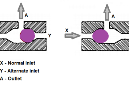
Some 3-way valves select fluid flow paths as in Above Figure. Use a spool-type valve for this operation. Another flow condition is the diverter valve shown in Below Figure. A diverter valve sends fluid to either of two paths.