Inst ToolsInst ToolsInst Tools
  • Courses
  • Automation
    • PLC
    • Control System
    • Safety System
    • Communication
    • Fire & Gas System
  • Instrumentation
    • Design
    • Pressure
    • Temperature
    • Flow
    • Level
    • Vibration
    • Analyzer
    • Control Valve
    • Switch
    • Calibration
    • Erection & Commissioning
  • Interview
    • Instrumentation
    • Electrical
    • Electronics
    • Practical
  • Q&A
    • Instrumentation
    • Control System
    • Electrical
    • Electronics
    • Analog Electronics
    • Digital Electronics
    • Power Electronics
    • Microprocessor
  • Request
Search
  • Books
  • Software
  • Projects
  • Process
  • Tools
  • Basics
  • Formula
  • Power Plant
  • Root Cause Analysis
  • Electrical Basics
  • Animation
  • Standards
  • 4-20 mA Course
  • Siemens PLC Course
Reading: Differential Pressure Sensor for Filtration Monitoring
Share
Font ResizerAa
Inst ToolsInst Tools
Font ResizerAa
  • Courses
  • Design
  • PLC
  • Interview
  • Control System
Search
  • Courses
  • Automation
    • PLC
    • Control System
    • Safety System
    • Communication
    • Fire & Gas System
  • Instrumentation
    • Design
    • Pressure
    • Temperature
    • Flow
    • Level
    • Vibration
    • Analyzer
    • Control Valve
    • Switch
    • Calibration
    • Erection & Commissioning
  • Interview
    • Instrumentation
    • Electrical
    • Electronics
    • Practical
  • Q&A
    • Instrumentation
    • Control System
    • Electrical
    • Electronics
    • Analog Electronics
    • Digital Electronics
    • Power Electronics
    • Microprocessor
  • Request
Follow US
All rights reserved. Reproduction in whole or in part without written permission is prohibited.
Inst Tools > Blog > Pressure Measurement > Differential Pressure Sensor for Filtration Monitoring

Differential Pressure Sensor for Filtration Monitoring

Last updated: December 5, 2019 10:03 am
Editorial Staff
Pressure Measurement
2 Comments
Share
2 Min Read
SHARE

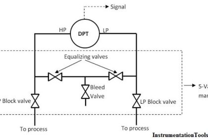
Differential pressure measurement is the difference in pressure between two points in a system.

Contents
How It Works :Example: Water Filtration System

For filtration applications, the upstream side [A] is positioned before the filter [B], whereas the downstream side [C] is after the filter.

A differential pressure sensor can be used to monitor the cleanliness of a filter in either liquid or gas applications.

Differential Pressure Sensor for Filtration Monitoring

How It Works :

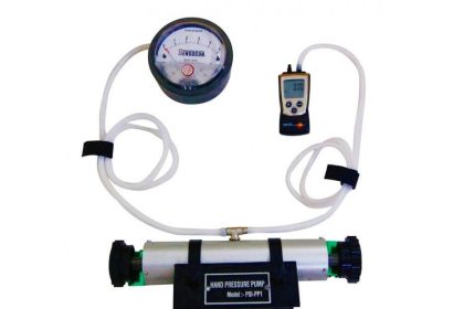
  1. The upstream pressure (commonly referred to as the line pressure or influent pressure) drives the media through the filter. A line is installed before the filter, as well as connected to the High side of the sensor.
  2. The filter then removes contaminants from the media.
  3. Next, the downstream pressure or effluent pressure, leads the media through the system with fewer contaminants than before. A line is installed on the Low side of the sensor in order to monitor the differential.
  4. When the filter is free of contaminants, the system will measure 0 PSI differential in pressure. As the filter becomes clogged, the pressure on the downstream side reduces, which creates a greater differential between the High and Low sides.While using the differential pressure sensor, the unit will offer a linear output signal based on the differential pressure.

Example: Water Filtration System

A 100 PSI pump with a filter is installed to purify the water for drinking. If the downstream side in the system pressure drops to 80 PSI, the filter should be cleaned or maintenance required.

With a 24VDC supply powering the sensor and a 4-20mA output signals elected, the sensor will be calibrated with a 100 PSI line pressure and 20 PSI differential pressure.

When the system is operating with a clean filter, the output signal will be 4mA. As the pressure decreases on the downstream, the output signal will increase.

Once the downstream pressure has been reduced to 80 PSI, the sensor’s output signal will reach the full scale of 20mA. When connected to a controller/HMI, the operator understands when to replace the filter.

Don't Miss Our Updates
Be the first to get exclusive content straight to your email.
We promise not to spam you. You can unsubscribe at any time.
Invalid email address
You've successfully subscribed !

Continue Reading

When to use a Diaphragm Seal?
3 Valve Manifold Operation
Bellows
How Capacitive Pressure Sensor Works ?
Inclined-limb Manometer Principle
Difference Between Absolute and Gauge Pressure
Share This Article
Facebook Whatsapp Whatsapp LinkedIn Copy Link
Share
2 Comments
  • Yash Khetiya says:
    August 11, 2016 at 2:28 am

    Your articles shows a in depth knowledge and understanding about various concepts of instrumentation. Thank you so much for showing up.

    Reply
    • raj says:
      September 13, 2016 at 5:36 am

      Great info.

      Reply

Leave a Reply Cancel reply

Your email address will not be published. Required fields are marked *

Stay Connected

128.3kFollowersLike
69.1kFollowersFollow
210kSubscribersSubscribe
38kFollowersFollow

Categories

Explore More

Information on the Pressure Gauge Dial
Impulse Line – Purpose & Tapping Point Location
Well Manometer Principle
DP Transmitter Block and Bleed Valves
Top 30 Interview Questions on Pressure Measuring Devices
Differential Pressure Switch Principle
Effects of Symmetric and Asymmetric Capillary Tube Pressure Measurement
U-tube Manometer with equal & unequal limb types

Keep Learning

Pressure and Temperature Gauges

Pressure and Temperature Gauges

Pressure Measurement Interview Questions

Interview Questions on Pressure Measurement

Pressure Transmitter Troubleshooting Tips

Pressure Transmitter Troubleshooting Tips

Force Balance Pressure Transmitters

Pneumatic Pressure Transmitters Principle

5-valve manifold

Pressure Transmitter Vent fittings

Pressure Sensor Temperature Effects

Temperature Compensation for Pressure Measurement

Pressure Gauge Water traps and pigtail siphons

Pressure Gauge Water Traps and Pigtail Siphons

Pressure Measurement Objective Questions

Pressure Measurement Objective Questions

Learn More

Seven Segment LED Display

Difference Between Common Cathode and Common Anode 7 Segment LED Display?

Digital Electronics Multiple Choice Questions

Design of Combinational Circuits Objective Questions

PLC Program three-phase electric motor

Identify the Problem in the PLC Program

Schematic Diagram

Schematic Diagram

How to Filter Digital and Analog Inputs in a PLC

How to Filter Digital and Analog Inputs in a PLC?

Parallel Circuit

Parallel Circuit

PLC Hoist Crane Programming

PLC Hoist Crane Programming: Example using Schneider

Inductor Principle

Inductance and Inductive Reactance

Menu

  • About
  • Privacy Policy
  • Copyright

Quick Links

  • Learn PLC
  • Helping Hand
  • Part Time Job

YouTube Subscribe

Follow US
All rights reserved. Reproduction in whole or in part without written permission is prohibited.
Welcome Back!

Sign in to your account

Username or Email Address
Password

Lost your password?