If a fault develops in a piece of electrical or electronic equipment located in an area where flammable gases are present the fault could cause heat or sparks sufficient to ignite the gas and cause a disaster. There are 2 systems in general use to prevent such happenings.
(a) Flameproof / Explosion proof equipment
The equipment is simply contained in a heavy protective enclosure, usually made of die cast steel, occasionally plastic. If heat or sparks from faulty equipment within the enclosure ignite flammable gas present with it the resulting explosion is contained within the enclosure. In North America metal conduit must be used for field wiring. In Europe and elsewhere suitably rated cable is connected directly to the equipment using certified flame proof cable glands.
Advantage – simple to design the system, suitable for high power equipment
Disadvantage – equipment becomes extremely heavy & expensive; opening the enclosure while powered is not permitted
(b) Intrinsically Safe
This approach limits the energy available to the intrinsically safe (I.S.) equipment, usually less than 2 watts, by means of a galvanic or zener barrier in such a way that under no circumstance will the equipment be able to generate sufficient heat or sparks to ignite flammable gases. Both the I.S. equipment and the zener barrier must be certified ‘Intrinsically Safe’ by BASEEFA, SIRA or a similar authority..
Advantage – considerably cheaper than comparable flame proof / explosion proof equipment, no special cabling required. Live maintenance permitted, no need to shut down the plant
Disadvantage – only suitable for low power equipment e.g. sounders, beacons and smoke detectors (which must be certified Intrinsically Safe)
Flame proof / Explosion proof (ATEX & ICEX equipment certified Exd & North American Class 1 Division 2 equipment)
i. The terms ‘explosion proof’ and ‘flameproof’ are largely interchangeable. Although there are some subtle differences, engineers and the market in general usually use both terms to mean the same thing, i.e. a piece of electrical equipment designed for use in a hazardous area by means of heavy duty enclosure.
ii. The cabling of any system employing ATEX or ICEX Exd certified equipment e.g. E2S Ltd. BEX series sounders or GNEX series xenon beacon, must use suitably rated and mechanically protected cable. The cable must be terminated using Exd certified cable glands and junction boxes. The glands and junction boxes must be certified Exd by BASEEFA, SIRA or similar recognised authority to the same level as the field equipment.
Intrinsically Safe Equipment (ATEX & ICEX equipment certified Exia, Exib, Exic & North American Class 1 Div 1 equipment)
Here safety in hazardous areas is achieved by using a zener barrier situated between the control panel and the device e.g. the E2S Ltd MiniAlarm sounders, or Apollo Orbis Series I.S. smoke detectors. The basic I.S. circuit is shown below:
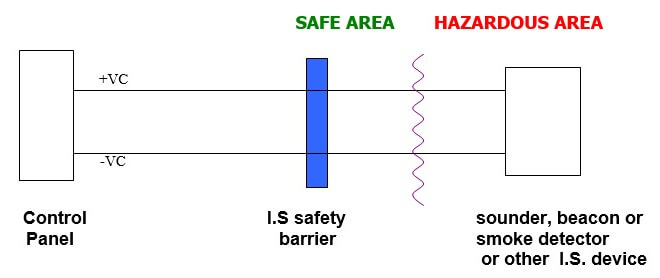
The manufacturer of the I.S. device will specify the type of I.S. safety barrier.
Connection cabling requirements
i. Although there are few restrictions on the type of cable used in IS circuits all cables have inductance and capacitance, and hence energy storage capabilities, thus they can affect system safety. The capacitance and inductance values of a given cable should be readily available from the cable manufacturer. In addition the capacitance and inductance values of the field mounted devices such as IS sounders and smoke detectors, must also be taken into account, again the values should be readily available from the manufacturer Consequently the system design imposes restrictions on the amount of each of these parameters. A great deal has been written on this subject but only rarely is there a serious limitation placed on the available cable.
ii. The cabling must conform to the following requirements
a. have protection from mechanical damage
b. have protection from chemical attack e.g. acids etc.
c. be securely fixed
d. have a minimum conductor size of 0.017mm2
e. must withstand 500V insulation test
f. circuit voltage must not exceed 60V
iii. The following types of cables can be used:
a. screened instrument cable
b. multi core signal cable (e.g. telephone cable) subject to certain conditions relating to screening and earthing
c. multi core miniature electric cables
d. conventional cables with conventional insulating sheaf e.g. PVC with a minimum insulation thickness of 0.3mm.
iii. There are no special requirements for junction boxes used in intrinsically safe circuits. However they must be clearly identified as being part of an Intrinsically safe system
iv. Installation of cables used in intrinsically safe circuits:
The installation of IS devices and associated equipment must conform to IEC 60079-14
Cable trays, ducts and conduits carrying intrinsically safe circuits should be seperate from cable trays, ducts etc. carrying any other cables. Note that in the U.K. I.E.T. wiring regulations prohibit electrical services e.g. power and lighting circuit cabling to be carried in the same conduit or duct as IS circuits.
Installation of cables used in intrinsically safe circuits
It is usually considered good practice to separate cable trays, ducts and conduits carrying intrinsically safe circuits from trays and ducts carrying any other cables, e.g. telephones & computer cables. I.E.E. wiring regulations prohibit electrical services, e.g. power and lighting to be carried in the same conduit.
Acknowledgements & References:
The above notes are based on extracts from MTL application AN9003 ” A users guide to Intrinsic Safety” and “Interface Technology – Engineers Guide” published by Pepperal + Fuchs. We express our thanks to them in the compilation of these notes. These notes do not form part of any offer or contract. This information is provided for guidance only and should not be relied upon. Responsibility for safety and system design remains entirely with the end user. Always seek expert advice.
Article Source : lgmproducts


Thank you sir. Can you explain please weatherproof equipment and difference with flamproof?