Inst ToolsInst ToolsInst Tools
  • Courses
  • Automation
    • PLC
    • Control System
    • Safety System
    • Communication
    • Fire & Gas System
  • Instrumentation
    • Design
    • Pressure
    • Temperature
    • Flow
    • Level
    • Vibration
    • Analyzer
    • Control Valve
    • Switch
    • Calibration
    • Erection & Commissioning
  • Interview
    • Instrumentation
    • Electrical
    • Electronics
    • Practical
  • Q&A
    • Instrumentation
    • Control System
    • Electrical
    • Electronics
    • Analog Electronics
    • Digital Electronics
    • Power Electronics
    • Microprocessor
  • Request
Search
  • Books
  • Software
  • Projects
  • Process
  • Tools
  • Basics
  • Formula
  • Power Plant
  • Root Cause Analysis
  • Electrical Basics
  • Animation
  • Standards
  • 4-20 mA Course
  • Siemens PLC Course
Reading: Dependent Current Source
Share
Font ResizerAa
Inst ToolsInst Tools
Font ResizerAa
  • Courses
  • Design
  • PLC
  • Interview
  • Control System
Search
  • Courses
  • Automation
    • PLC
    • Control System
    • Safety System
    • Communication
    • Fire & Gas System
  • Instrumentation
    • Design
    • Pressure
    • Temperature
    • Flow
    • Level
    • Vibration
    • Analyzer
    • Control Valve
    • Switch
    • Calibration
    • Erection & Commissioning
  • Interview
    • Instrumentation
    • Electrical
    • Electronics
    • Practical
  • Q&A
    • Instrumentation
    • Control System
    • Electrical
    • Electronics
    • Analog Electronics
    • Digital Electronics
    • Power Electronics
    • Microprocessor
  • Request
Follow US
All rights reserved. Reproduction in whole or in part without written permission is prohibited.
Inst Tools > Blog > Electronic Devices & Circuits > Dependent Current Source

Dependent Current Source

Last updated: October 6, 2016 6:25 am
Editorial Staff
Electronic Devices & Circuits
No Comments
Share
1 Min Read
SHARE

A dependent current source establishes a current, which is independent of the voltage across it, that is determined by the voltage or current at some other location in the electrical system. There are two types of dependent current source  –  the  voltage controlled  current  source  (VCCS)  and  the  current controlled current source (CCCS).

Dependent Current Source

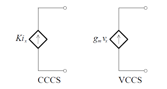
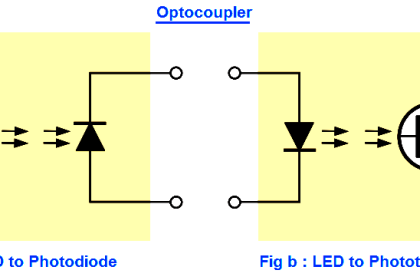
These  sources  are  mathematical  models  that  are  useful  in  modelling  real circuits and systems, e.g. they are used in modelling transistors.

Example:

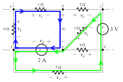
Consider the circuit shown below. In this circuit the value of the dependent current source is specified by a voltage – it is a VCCS.

dependent-current-source-circuit-example

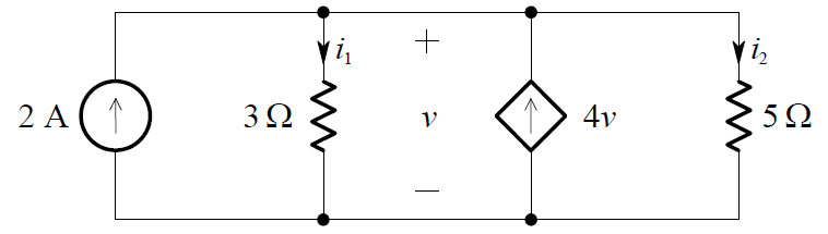
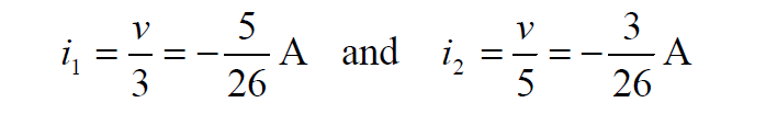
To solve for v, we apply KCL and obtain:

i1 + i2  = 4v + 2

Thus:

dependent-current-source-equation

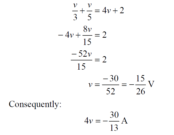
and this is the value of the dependent current source, in amperes. The other variables in the circuit are:

dependent-current-source-equation-2

Don't Miss Our Updates
Be the first to get exclusive content straight to your email.
We promise not to spam you. You can unsubscribe at any time.
Invalid email address
You've successfully subscribed !

Continue Reading

Semiconductors Diodes Questions & Answers
Light Emitting Diode Operation
pi filter Operation
Transistor Collector Feedback Bias
Basics of Ohm’s Law
Transistor Collector Characteristic Curves
Share This Article
Facebook Whatsapp Whatsapp LinkedIn Copy Link
Share
Leave a Comment

Leave a Reply Cancel reply

Your email address will not be published. Required fields are marked *

Stay Connected

128.3kFollowersLike
69.1kFollowersFollow
210kSubscribersSubscribe
38kFollowersFollow

Categories

Explore More

Full Wave Bridge Rectifier Operation
Combining Independent Current Sources in Parallel
What is a Memristor? Principle, Advantages, Applications
Freewheeling Diode Working Principle
Power MOSFET Safe Operating Area
Short Notes on Rectifiers & Filters
Dependent Voltage Source
Comparison of MOSFET and BJT

Keep Learning

temperature compensation circuit for PMMC

PMMC Temperature Compensation

Transistor Load Line Analysis

Transistor Load Line Analysis

Zener Diode Voltage Regulator Operation

Zener Diode Voltage Regulator Operation

half-wave-rectifier-working-animation

Half Wave Rectifier Principle

principle of time base generator

Time Base Generator

diode-limiter-principle

Diode Limiters/Clippers Operation

energy-diagrams-for-insulator-semiconductor-and-conductor

Band Gap for Semiconductor Materials

phototransistor symbols

Phototransistor Working Principle

Learn More

water treatment station

What is a Vent Filter? – Water Treatment Plant

V Cone Flow Meter Working Principle

V Cone Flow Meter – Principle, Advantages, Disadvantages

DP transmitter Elevated 10 Feet above the Vessel

DP transmitter Elevated 10 Feet above the Vessel

Arc Fault Breaker (AFB) Electrical Problem Solved

Premature Arc Fault Breaker Failures

Ladder Logic for Motor Control

PLC Programming for 3 Motors control in Ladder logic

Displacer Level Measurement Formula

Displacer Level Measurement Calculations

How to Connect HART Communicator with DP Transmitter

15 HART Communicator Questions

LED Projects for Engineering Students

LED Projects for Engineering Students

Menu

  • About
  • Privacy Policy
  • Copyright

Quick Links

  • Learn PLC
  • Helping Hand
  • Part Time Job

YouTube Subscribe

Follow US
All rights reserved. Reproduction in whole or in part without written permission is prohibited.
Welcome Back!

Sign in to your account

Username or Email Address
Password

Lost your password?