Inst ToolsInst ToolsInst Tools
  • Courses
  • Automation
    • PLC
    • Control System
    • Safety System
    • Communication
    • Fire & Gas System
  • Instrumentation
    • Design
    • Pressure
    • Temperature
    • Flow
    • Level
    • Vibration
    • Analyzer
    • Control Valve
    • Switch
    • Calibration
    • Erection & Commissioning
  • Interview
    • Instrumentation
    • Electrical
    • Electronics
    • Practical
  • Q&A
    • Instrumentation
    • Control System
    • Electrical
    • Electronics
    • Analog Electronics
    • Digital Electronics
    • Power Electronics
    • Microprocessor
  • Request
Search
  • Books
  • Software
  • Projects
  • Process
  • Tools
  • Basics
  • Formula
  • Power Plant
  • Root Cause Analysis
  • Electrical Basics
  • Animation
  • Standards
  • 4-20 mA Course
  • Siemens PLC Course
Reading: How to Check the Continuity of Protective Conductors?
Share
Notification Show More
Font ResizerAa
Inst ToolsInst Tools
Font ResizerAa
  • Courses
  • Design
  • PLC
  • Interview
  • Control System
Search
  • Courses
  • Automation
    • PLC
    • Control System
    • Safety System
    • Communication
    • Fire & Gas System
  • Instrumentation
    • Design
    • Pressure
    • Temperature
    • Flow
    • Level
    • Vibration
    • Analyzer
    • Control Valve
    • Switch
    • Calibration
    • Erection & Commissioning
  • Interview
    • Instrumentation
    • Electrical
    • Electronics
    • Practical
  • Q&A
    • Instrumentation
    • Control System
    • Electrical
    • Electronics
    • Analog Electronics
    • Digital Electronics
    • Power Electronics
    • Microprocessor
  • Request
Follow US
All rights reserved. Reproduction in whole or in part without written permission is prohibited.
Inst Tools > Blog > Electrical Basics > How to Check the Continuity of Protective Conductors?

How to Check the Continuity of Protective Conductors?

Learn how to check the continuity of protective conductors effectively to ensure electrical safety in your systems and panels.

Last updated: June 6, 2025 4:23 pm
Viral Nagda
Electrical Basics
No Comments
Share
6 Min Read
SHARE

Most of the time, engineers get confused as to what a protective conductor is. Basically, a protective conductor is nothing but an earthing wire connected between two earthing points. As we know, earthing is a very important point in an electrical panel as it protects the circuit from leakage current or residual current. Due to this, any untoward incident like an electric shock or damage to the electrical equipment, is protected. So, checking the connection of protective conductors is a very important part of electrical engineering. It aims to check the continuity of the wire between two earthing points, ensuring that there is no via break, and in case of any earth fault, the leakage current will safely pass to the main earthing pit. In this post, we will see how to check the continuity of a protective conductor.

Contents
What is a protective conductor?How to check the continuity of protective conductors?

What is a protective conductor?

First of all, let us understand what a protective conductor is. You must have seen that any electrical equipment has a point to connect the earth wire to it. So, a protective conductor is nothing but a wire that connects that point to the main earth point. Due to this, all the leakage current or residual current that flows in the equipment due to any malfunction will be safely passed on to the main earthing point. This prevents any incident of an electrical shock. It is usually coloured green and yellow striped according to IEC standards. One thing to note is that the resistance of the protective conductor must be very low, because if it is high, then the current will not be able to flow from that wire to the main earthing point. This will make the conductor useless.

What makes continuity testing of protection conductors special is that, apart from checking the connection between two earth points, this test also requires checking the resistance between those two points. There is no use if the wires are joined, but the resistance is very high. This will increase the risk levels and cause any dangerous hazards. In normal continuity, we only check the joint connection between two points. But this is not the case with protective conductors.

How to check the continuity of protective conductors?

Now, let us come to the main topic. First of all, to check our thing, you will require two main settings in a multimeter – continuity and resistance.

Let us consider the scenario like this – there is an electrical panel which has the following components: of motor cabinet and an earth bar. The motor cabinet has an earthing point, which allows the earthing wire to be connected. We will connect one end of the wire to the motor cabinet point, and the other end to the earth bar. We will assume that we have already checked the continuity between the earth bar and the main plant earthing pit. So, any wire connected to the earth bar automatically ensures that your earthing point has been safely grounded to the main ground pit of your factory.

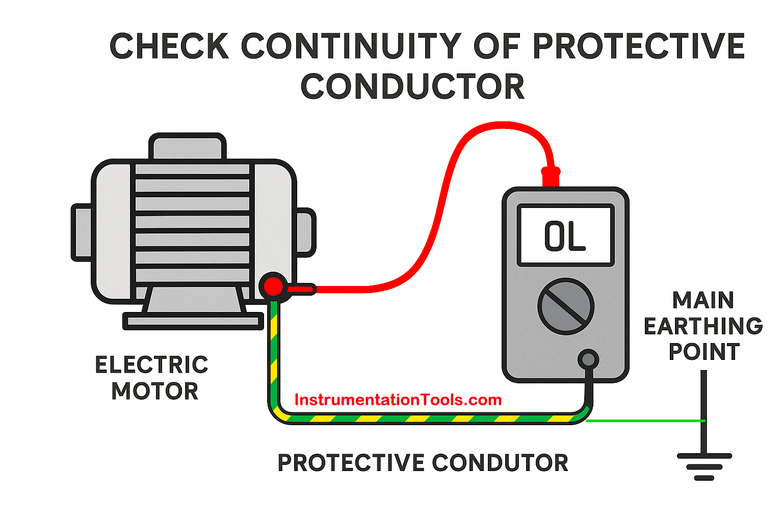
First of all, you need to power off the whole panel. Now, you need to connect one end of the multimeter to the motor cabinet earthing point and the other end to the earth bar. Set the multimeter setting to continuity. If there is a beep sound, that means the wire has been properly connected to both joints. Now, set the multimeter setting to resistance. The value should be less than 1 ohm. This will ensure that a low-resistance path will be provided to any leakage current happening in the motor equipment, thus allowing for safe passage of that leakage current to ground. Out of the two criteria of continuity or resistance, if any one fails, then the continuity of a productive conductor overall has failed. Refer to the image below for more details.

How to Check the Continuity of Protective Conductors

As the distance between two points increases, a slight increase in resistance will be expected. For example, 0.3 ohms can become 0.4 ohms. But the maximum tolerable resistance must always be less than 1 ohms, and should not increase beyond that point.

Practically speaking, the distance between the main earth pit and any earthing point on a panel or point is large and usually more than 5 meters. A multimeter probe is usually 1-2 meters. So, you have to use long wires with alligator clips to make a long and continuous probe connection. You can even use a loop impedance tester, which can check continuity for earth connections. But be it anything, be sure to do all your testing in a power-disconnected state, for safety purposes and also, best results. So, due to the sensitivity of the earth wire conductor or protective conductor, its continuity and resistance checking play a very important role in electrical systems.

In this way, we saw how to check the continuity of protective conductors.

Read Next:

  • Automatic Transfer Switch Electrical Circuit
  • What is Electrical Panel Door Earth Bonding?
  • Emergency STOP vs. Emergency Power OFF
  • Why Connect Transformers in Parallel?
  • How to Protect Electrical Terminal Blocks?

Don't Miss Our Updates
Be the first to get exclusive content straight to your email.
We promise not to spam you. You can unsubscribe at any time.
Invalid email address
You've successfully subscribed !

Continue Reading

Difference Between Flame Resistant and Flame Retardant Cables
Motor Forward and Reverse Direction Control using Limit Switches
What is a Time Delay Fuse? – Principles and Advantages
Top 100 Power Systems Projects – Electrical Engineering
How does Electrical Power Outlet Work?
Electrical Terminology
Share This Article
Facebook Whatsapp Whatsapp LinkedIn Copy Link
Share
Leave a Comment

Leave a Reply Cancel reply

Your email address will not be published. Required fields are marked *

Stay Connected

128.3kFollowersLike
69.1kFollowersFollow
210kSubscribersSubscribe
38kFollowersFollow

Categories

Explore More

Why Circuit Breakers Don’t Protect People?
What is a Semiconductor Fuse?
How Do Air Compressor Filters Clean and Protect the System?
What is an Instrument Transformer? – Types, Principle, Advantages
Why CT Secondary Should Never Be Kept Open?
Difference Between AA and AAA Batteries
UPS Working Principle and Types – Offline and Online UPS Systems
Why is Motor Control Required in Control Systems?

Keep Learning

Routine Tests of Transformers

Transformer Testing – Routine Tests of Transformers

Why is IGBT used in VFD

Why is IGBT used in VFD?

Top 100 Electrical Machines Projects for Electrical Engineers

Top 100 Electrical Machines Projects for Electrical Engineers

What is ELCB

What is ELCB? Principle, Advantages, Disadvantages, Applications

Motor Maintenance

Motor Maintenance, Troubles, Regular Checks, Performance

Difference between Signal Cables and Control Cables

Difference between Signal Cables and Control Cables

Types of MCB

Types of MCB

What is Trunking

Difference Between Trunking and Conduit

Learn More

Level Measurement Objective Questions

Level and Density Measurement Objective Questions

Photodiode as Variable Resistance Device

Photodiode as Variable Resistance Device

Pros and Cons of Online Educational Services

Pros and Cons of Online Courses

Filters in Compressors

Filters in Compressors

Stability and Uniformity of Temperature Bath

Stability and Uniformity of Temperature Bath

Integral Orifice Parts

What is Integral Flow Orifice Assembly?

Full Wave Rectifier Peak Inverse Voltage

Full Wave Bridge Rectifier Peak Inverse Voltage

Paddlewheel flowmeter principle

What is a Paddle Wheel Flow Meter?

Menu

  • About
  • Privacy Policy
  • Copyright

Quick Links

  • Learn PLC
  • Helping Hand
  • Part Time Job

YouTube Subscribe

Follow US
All rights reserved. Reproduction in whole or in part without written permission is prohibited.
Welcome Back!

Sign in to your account

Username or Email Address
Password

Lost your password?