Any two conductors separated by an insulating medium constitutes a condenser or capacitor.In case of overhead transmission lines, two conductors form the two plates of the capacitor and the air between the conductors behaves as dielectric medium. Thus an overhead transmission line can be assumed to have capacitance between the conductors throughout the length of the line. The capacitance is uniformly distributed over the length of the line and may be considered as uniform series of condensers connected between the conductors.
When an alternating voltage is applied across the transmission line it draws the leading current even when supplying no load. This leading current will be in quadrature with the applied voltage and is termed as charging current. It must be noted that charging current is due to the capacitive effect between the conductors of the line and does not depend on the load. The strength of the charging currents depends on the voltage of transmission, the capacitance of the line and frequency of the ac supply. It is given by the expression
Charging current Ic = 2 . pi . f . C . V
Where f is the frequency of the supply
C is the Capacitance of the line
V is the voltage of the line
If the capacitance of the overhead line is high, the line draws more charging currents which cancels out the lagging component of the load current (normally load is inductive in nature). Hence the resultant current flowing in the line is reduced. The reduction in the resultant current flowing through the transmission line for given load current results in:
Significance of Charging currents:
Capacitance effect (responsible for charging currents) of the short transmission lines are negligible. However they are significant in medium and long distance transmission lines.
In long distance transmission lines, during light loaded conditions receiving end voltage will be higher than sending end voltage. This is because of the charging currents and capacitive effect of the line
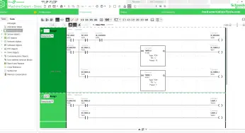
Learn the example of flip-flop PLC program for lamps application using the ladder logic to…
In this article, you will learn the STAR DELTA programming using PLC controller to start…
Lube oil consoles of rotary equipment packages in industrial process plants are usually equipped with…
Rotating equipment packages such as pumps, compressors, turbines need the lube oil consoles for their…
This article explains how to blink lights in ladder logic with a detailed explanation video…
In this article, a simple example will teach you the conversion from Boolean algebra to…
View Comments
Nice,but not sufficient