Inst ToolsInst ToolsInst Tools
  • Ask
  • Courses
  • Videos
  • Q & A
    • Interview
      • Instrumentation
      • Electronics
      • Electrical
      • Practical Questions
    • MCQ
      • Instrumentation MCQ
      • Electrical MCQ
      • Electronics MCQ
      • Control Systems MCQ
      • Analog Electronics MCQ
      • Digital Electronics MCQ
      • Power Electronics MCQ
      • Microprocessor MCQ
      • Multiple Choice Questions
  • EE
    • Electronics
      • Electronics Q & A
      • Electronic Basics
      • Electronic Devices & Circuits
      • Electronics Animation
      • Digital Electronics
    • Electrical
      • Electrical Basics
      • Electrical Q & A
      • Power Electronics
      • Electrical Machines
      • Electrical Animation
      • Power Systems
      • Switchgear & Protection
      • Transmission & Distribution
  • Measure
    • Control Valves
    • Calibration
    • Temperature
    • Pressure
    • Flow
    • Level
    • Analyzers
    • Switches
    • Vibration
    • Solenoid Valve
  • Control
    • PLC Tutorials
    • Control Systems
    • Safety Instrumented System (SIS)
    • Communication
    • Fire & Gas System
  • More
    • Design
    • Tools
    • Animation
    • Basics
    • Formulas
    • Standards
    • TextBooks
    • Common
    • Software
    • Excel Tools
    • Erection & Commissioning
    • Process Fundamentals
    • Videos
    • Books
Search
All rights reserved. Reproduction in whole or in part without written permission is prohibited.
Reading: Capacitively Coupled Multistage Transistor Amplifier
Share
Notification Show More
Font ResizerAa
Inst ToolsInst Tools
Font ResizerAa
  • Courses
  • PLC Tutorials
  • Control Systems
Search
  • Ask
  • Courses
  • Videos
  • Q & A
    • Interview
    • MCQ
  • EE
    • Electronics
    • Electrical
  • Measure
    • Control Valves
    • Calibration
    • Temperature
    • Pressure
    • Flow
    • Level
    • Analyzers
    • Switches
    • Vibration
    • Solenoid Valve
  • Control
    • PLC Tutorials
    • Control Systems
    • Safety Instrumented System (SIS)
    • Communication
    • Fire & Gas System
  • More
    • Design
    • Tools
    • Animation
    • Basics
    • Formulas
    • Standards
    • TextBooks
    • Common
    • Software
    • Excel Tools
    • Erection & Commissioning
    • Process Fundamentals
    • Videos
    • Books
Follow US
All rights reserved. Reproduction in whole or in part without written permission is prohibited.
Inst Tools > Blog > Electronic Devices & Circuits > Capacitively Coupled Multistage Transistor Amplifier

Capacitively Coupled Multistage Transistor Amplifier

Last updated: September 27, 2016 5:11 am
Editorial Staff
Electronic Devices & Circuits
No Comments
Share
2 Min Read
SHARE

Two or more amplifiers can be connected in a cascaded arrangement with the output of one amplifier driving the input of the next. Each amplifier in a cascaded arrangement is known as a stage. The basic purpose of a multistage arrangement is to increase the overall voltage gain.

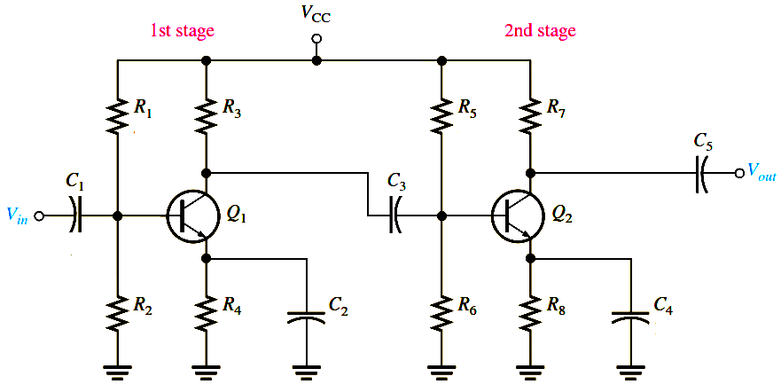
For purposes of illustration, we will use the two-stage capacitively coupled amplifier in Figure. Note that both stages are identical common-emitter amplifiers with the output of the first stage capacitively coupled to the input of the second stage. Capacitive coupling prevents the dc bias of one stage from affecting that of the other but allows the ac signal to pass without attenuation because XC = 0 ohms at the frequency of operation. Notice, also, that the transistors are labeled Q1 and Q2.

Capacitively Coupled Multistage Transistor Amplifier

Loading Effects

In determining the voltage gain of the first stage, you must consider the loading effect of the second stage. Because the coupling capacitor C3 effectively appears as a short at the signal frequency, the total input resistance of the second stage presents an ac load to the first stage. Looking from the collector of Q1, the two biasing resistors in the second stage, R5 and R6, appear in parallel with the input resistance at the base of Q2.

In other words, the signal at the collector of Q1 “sees” R3, R5, R6, and Rin(base2) of the second stage all in parallel to ac ground. Thus, the effective ac collector resistance of Q1 is the total of all these resistances in parallel. The voltage gain of the first stage is reduced by the loading of the second stage because the effective ac collector resistance of the first stage is less than the actual value of its collector resistor, R3.

Don't Miss Our Updates
Be the first to get exclusive content straight to your email.
We promise not to spam you. You can unsubscribe at any time.
Invalid email address
You've successfully subscribed !

Recommended Articles

How the Matrix Keypad works with a Micro controller?
PIN Diode Working Principle
What is Kirchhoff’s Voltage Law
Transistor Biasing
Optocouplers Working Principle
Transistor Voltage Divider Bias
Share This Article
Facebook Whatsapp Whatsapp LinkedIn Copy Link
Share
Leave a Comment

Leave a Reply Cancel reply

Your email address will not be published. Required fields are marked *

Stay Connected

128.3kFollowersLike
69.1kFollowersFollow
208kSubscribersSubscribe
38kFollowersFollow

Categories

Recent Comments

  • William Snyder on Top Non-PLC Certification Courses for Automation Professionals
  • Kamli on Top Free PLC Software
  • Guifty Shimica on Top Non-PLC Certification Courses for Automation Professionals
  • Guifty Shimica on Top Non-PLC Certification Courses for Automation Professionals

Related Articles

Voltage Divider Rule

Voltage Divider Rule

What is a Filter Circuit

What is a Filter Circuit ?

temperature compensation circuit for PMMC

PMMC Temperature Compensation

Shockley Diode Working Principle

Shockley Diode Working Principle

Transistor Collector Characteristic Curves

Transistor Collector Characteristic Curves

Optoisolator Working Principle

Optoisolator Working Principle

transistor-biasing-circuits

Summary Of Transistor Bias Circuits

Short Circuit and Open Circuit

Short Circuit and Open Circuit

More Articles

Robotic Process Automation

What is Robotic Process Automation? Advantages, Applications

Selection Criteria of PH Analyzer

Selection Criteria of pH Analyzers

Digital Electronics Multiple Choice Questions

Triggering of Flip Flops Objective Questions

Thermistors and Resistance Temperature Detectors (RTDs)

Thermistors and Resistance Temperature Detectors (RTDs)

Proximity Transducer Operation

Proximity Transducer System Operation

Programmable Logic Controllers Multiple Choice Questions

Programmable Logic Controllers Multiple Choice Questions

Modbus Communication Interview Questions and Answers

Modbus Communication Interview Questions and Answers

Mass Spectrometer Questions and Answers

Time of Flight Mass Spectrometer

Follow US
All rights reserved. Reproduction in whole or in part without written permission is prohibited.
Welcome Back!

Sign in to your account

Username or Email Address
Password

Lost your password?