Inst ToolsInst ToolsInst Tools
  • Ask
  • Courses
  • Videos
  • Q & A
    • Interview
      • Instrumentation
      • Electronics
      • Electrical
      • Practical Questions
    • MCQ
      • Instrumentation MCQ
      • Electrical MCQ
      • Electronics MCQ
      • Control Systems MCQ
      • Analog Electronics MCQ
      • Digital Electronics MCQ
      • Power Electronics MCQ
      • Microprocessor MCQ
      • Multiple Choice Questions
  • EE
    • Electronics
      • Electronics Q & A
      • Electronic Basics
      • Electronic Devices & Circuits
      • Electronics Animation
      • Digital Electronics
    • Electrical
      • Electrical Basics
      • Electrical Q & A
      • Power Electronics
      • Electrical Machines
      • Electrical Animation
      • Power Systems
      • Switchgear & Protection
      • Transmission & Distribution
  • Measure
    • Control Valves
    • Calibration
    • Temperature
    • Pressure
    • Flow
    • Level
    • Analyzers
    • Switches
    • Vibration
    • Solenoid Valve
  • Control
    • PLC Tutorials
    • Control Systems
    • Safety Instrumented System (SIS)
    • Communication
    • Fire & Gas System
  • More
    • Design
    • Tools
    • Animation
    • Basics
    • Formulas
    • Standards
    • TextBooks
    • Common
    • Software
    • Excel Tools
    • Erection & Commissioning
    • Process Fundamentals
    • Videos
    • Books
Search
All rights reserved. Reproduction in whole or in part without written permission is prohibited.
Reading: Calculate the Voltage across Voltmeters of Thermocouple
Share
Notification Show More
Font ResizerAa
Inst ToolsInst Tools
Font ResizerAa
  • Courses
  • PLC Tutorials
  • Control Systems
Search
  • Ask
  • Courses
  • Videos
  • Q & A
    • Interview
    • MCQ
  • EE
    • Electronics
    • Electrical
  • Measure
    • Control Valves
    • Calibration
    • Temperature
    • Pressure
    • Flow
    • Level
    • Analyzers
    • Switches
    • Vibration
    • Solenoid Valve
  • Control
    • PLC Tutorials
    • Control Systems
    • Safety Instrumented System (SIS)
    • Communication
    • Fire & Gas System
  • More
    • Design
    • Tools
    • Animation
    • Basics
    • Formulas
    • Standards
    • TextBooks
    • Common
    • Software
    • Excel Tools
    • Erection & Commissioning
    • Process Fundamentals
    • Videos
    • Books
Follow US
All rights reserved. Reproduction in whole or in part without written permission is prohibited.
Inst Tools > Blog > Practical Questions > Calculate the Voltage across Voltmeters of Thermocouple

Calculate the Voltage across Voltmeters of Thermocouple

Last updated: June 6, 2018 9:48 am
Editorial Staff
Practical Questions
No Comments
Share
3 Min Read
SHARE

Suppose three different voltmeters are connected to a thermocouple, with each voltmeter having a different ambient temperature:

Calculate the amount of voltage at Thermocouple

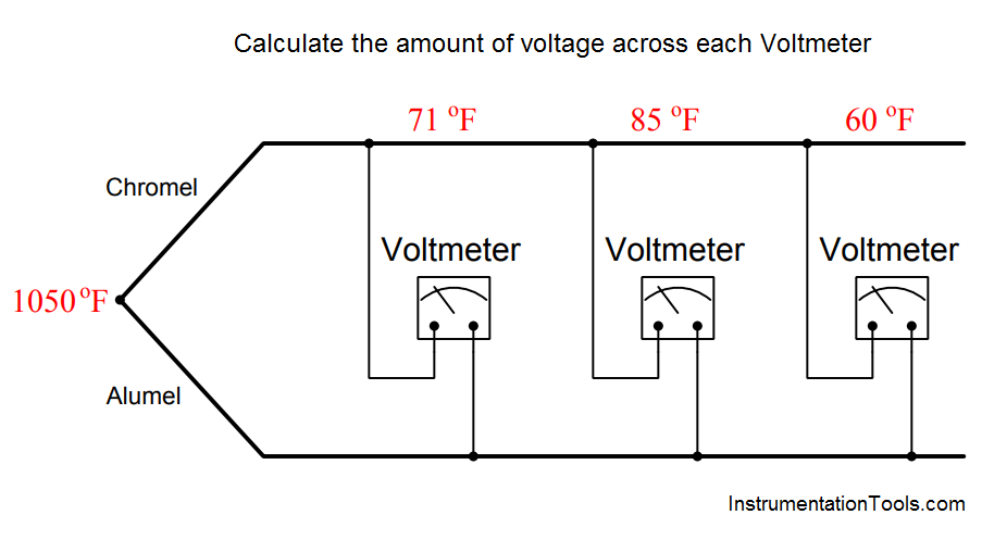
Calculate the amount of voltage registered by each of the three voltmeters, as well as answer the following questions:

  1. If a fourth voltmeter were connected to this same thermocouple, would it affect the readings of the other three?
  2. If a thermocouple transmitter were connected to this thermocouple, would it affect the readings of the voltmeters? Would it matter whether or not this transmitter were equipped with reference junction compensation?

Answer :

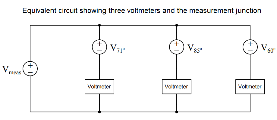
Each voltmeter forms its own reference junction where the copper wires of each voltmeter connect to the chromel and alumel thermocouple wires. Each voltmeter’s reference junction produces its own voltage, opposed in polarity to the voltage of the measurement junction (at 1050 oF). This means we must perform a separate voltage calculation for each voltmeter based on each meter’s reference junction temperature.

An equivalent schematic diagram shows how the four dissimiar metal junctions relate to one another, and to the three voltmeters:

three voltmeters and the measurement junction

The chromel and alumel wire types identify this as a type K thermocouple, and so we may use a type K thermocouple table to look up voltages for all four junction temperatures:

  • Type K at 1050 oF = 23.439 mV
  • Type K at 71 oF = 0.865 mV
  • Type K at 85 oF = 1.181 mV
  • Type K at 60 oF = 0.619 mV

Since we know the measurement and reference junctions stand opposed to one another in each voltmeter loop, we may calculate each voltmeter’s reading by subtracting the reference junction’s voltage from the measurement junction’s voltage for each voltmeter:

Voltage registered by the left-hand voltmeter (at 71 oF):

23.439 mV − 0.865 mV = 22.574 mV

Voltage registered by the center voltmeter (at 85 oF):

23.439 mV − 1.181 mV = 22.258 mV

Voltage registered by the right-hand voltmeter (at 60 oF):

23.439 mV − 0.619 mV = 22.820 mV

The voltage read by each voltmeter is a simple function of Kirchhoff’s Voltage Law, with the measurement junction and the voltmeter’s reference junction being the only voltage sources in the KVL loop.

Therefore, connection of a fourth voltmeter will have no effect whatsoever on the other three voltmeters.

Likewise, connection of a thermocouple transmitter to this same chromel/alumel wire pair will have no effect on the voltmeters’ readings, with or without reference junction compensation.

Don't Miss Our Updates
Be the first to get exclusive content straight to your email.
We promise not to spam you. You can unsubscribe at any time.
Invalid email address
You've successfully subscribed !
Questions on Allen-Bradley MicroLogix 1000 PLC
Calculate the Magnitude of Hydrostatic Pressure
Determine the Pressure at Each Port of DP Transmitter
Practical Process Control System Questions & Answers – 7
Analytical Control System of Heat Exchanger Questions
Share This Article
Facebook Whatsapp Whatsapp LinkedIn Copy Link
Share
Leave a Comment

Leave a Reply Cancel reply

Your email address will not be published. Required fields are marked *

Stay Connected

128.3kFollowersLike
69.1kFollowersFollow
208kSubscribersSubscribe
38kFollowersFollow

Categories

Recent Comments

  • Guifty Shimica on Top Non-PLC Certification Courses for Automation Professionals
  • Guifty Shimica on Top Non-PLC Certification Courses for Automation Professionals
  • MIHARITSOA Aina Sitraka on Top Non-PLC Certification Courses for Automation Professionals
  • Vaishnavi on Free Instrumentation Course for Trainee Engineers

Related Articles

Foxboro model 13 DP transmitter

Re-calibrate the Foxboro DP Pneumatic Transmitter

Programmable Logic Controller (PLC) Questions and Answers

Programmable Logic Controller (PLC) Questions and Answers – 2

Pneumatic Relay

Pneumatic Relay Questions

surface-mounted water pump

Surface-mounted Water Pump

Which instrument is at fault in this system

Which Instrument is at Fault in this System?

Draw the Symbols for Liquid Level Measuring Instruments

Draw the Symbols for Liquid Level Measuring Instruments

Radar LT Loop Diagram

Questions on Radar LT Loop Diagram

Calculate Amount of Weight Indicated by the Scale

Calculate Amount of Weight Indicated by the Scale

More Articles

Profibus Communication Interview Questions & Answers

Profibus Communication Interview Questions & Answers

Chart Recorders

What is a Recorder ?

Time Response Analysis

State Variable Analysis – Part II

What are Fire Branches?

What are Fire Branches?

Distillation Tower Displacer Level Instrument

Distillation Tower Displacer Level Instrument Check

Instrument Junction Box

Instrumentation System Architecture

Pressure and Temperature Gauges

Pressure and Temperature Gauges

Steps in PLC System Design

Steps in PLC System Design

Follow US
All rights reserved. Reproduction in whole or in part without written permission is prohibited.
Welcome Back!

Sign in to your account

Username or Email Address
Password

Lost your password?