Inst ToolsInst ToolsInst Tools
  • Courses
  • Automation
    • PLC
    • Control System
    • Safety System
    • Communication
    • Fire & Gas System
  • Instrumentation
    • Design
    • Pressure
    • Temperature
    • Flow
    • Level
    • Vibration
    • Analyzer
    • Control Valve
    • Switch
    • Calibration
    • Erection & Commissioning
  • Interview
    • Instrumentation
    • Electrical
    • Electronics
    • Practical
  • Q&A
    • Instrumentation
    • Control System
    • Electrical
    • Electronics
    • Analog Electronics
    • Digital Electronics
    • Power Electronics
    • Microprocessor
  • Request
Search
  • Books
  • Software
  • Projects
  • Process
  • Tools
  • Basics
  • Formula
  • Power Plant
  • Root Cause Analysis
  • Electrical Basics
  • Animation
  • Standards
  • 4-20 mA Course
  • Siemens PLC Course
Reading: Bridge Rectifier Working Animation
Share
Font ResizerAa
Inst ToolsInst Tools
Font ResizerAa
  • Courses
  • Design
  • PLC
  • Interview
  • Control System
Search
  • Courses
  • Automation
    • PLC
    • Control System
    • Safety System
    • Communication
    • Fire & Gas System
  • Instrumentation
    • Design
    • Pressure
    • Temperature
    • Flow
    • Level
    • Vibration
    • Analyzer
    • Control Valve
    • Switch
    • Calibration
    • Erection & Commissioning
  • Interview
    • Instrumentation
    • Electrical
    • Electronics
    • Practical
  • Q&A
    • Instrumentation
    • Control System
    • Electrical
    • Electronics
    • Analog Electronics
    • Digital Electronics
    • Power Electronics
    • Microprocessor
  • Request
Follow US
All rights reserved. Reproduction in whole or in part without written permission is prohibited.
Inst Tools > Blog > Electronic Devices & Circuits > Bridge Rectifier Working Animation

Bridge Rectifier Working Animation

Last updated: September 27, 2016 5:34 am
Editorial Staff
Electronic Devices & Circuits Electronics Animation
No Comments
Share
2 Min Read
SHARE

What is Rectifier?

A rectifier is a device that simply converts alternating current (AC) into direct current (DC).

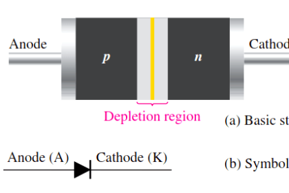
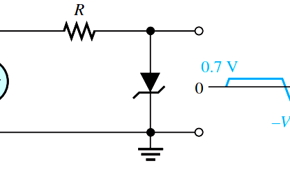
The way a rectifier changes AC to DC is by the use of a diode, or multiple diodes. Diodes only allow electrons to flow in one direction through them.

Diode Rectifier


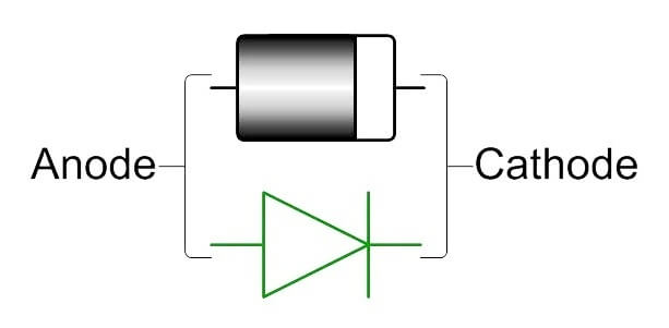
When the voltage on the anode is more positive than the voltage on the cathode, current will flow through the diode.  If the voltage is reversed, making the cathode more positive, then current will not flow through the diode.  (unless the peak reverse voltage rating is exceeded).

TYPES OF DIODE :

1) HALFWAVE RECTIFIER

On the first half of the cycle the diode allows the electrons to flow through it powering the DC load.  On the second half cycle the diode blocks the flow of electrons and the load receives no flow at all.

HALFWAVE RECTIFIER ANIMATION

2) FULL WAVE BRIDGE RECTIFIER

On the first half of our cycle the flow electrons passes through the bridge allowing electrons to flow to the load in one direction.  Then on the second half of the cycle the flows passes through the bridge recifier following a different path, but still sends the electron flow in the same direction to the load giving it twice the output of a single diode rectifier.  An RC filter (a resistor and a capacitor wired in parallel with the DC load) further smooths the output.

FULL WAVE BRIDGE RECTIFIER ANIMATION

Don't Miss Our Updates
Be the first to get exclusive content straight to your email.
We promise not to spam you. You can unsubscribe at any time.
Invalid email address
You've successfully subscribed !

Continue Reading

Transistor Collector Characteristic Curves
Choke Input Filter Operation
What is Kirchhoff’s Current Law
Cathode Ray Tube Deflection System
PIN Diode Working Principle
Full Wave Voltage Doubler using Diodes
Share This Article
Facebook Whatsapp Whatsapp LinkedIn Copy Link
Share
Leave a Comment

Leave a Reply Cancel reply

Your email address will not be published. Required fields are marked *

Stay Connected

128.3kFollowersLike
69.1kFollowersFollow
210kSubscribersSubscribe
38kFollowersFollow

Categories

Explore More

Capacitor Filter Working Principle
What is a Filter Circuit ?
Difference between ideal diode & conventional diode
How a PN Junction Formed in a Diode
JFET Working Animation
Zener Diode Voltage Regulator Operation
Schottky Diode Working Principle
Dependent Current Source

Keep Learning

Transistor Collector Feedback Bias

Transistor Collector Feedback Bias

Button 3C of the Matrix Keypad is pressed

How the Matrix Keypad works with a Micro controller?

Electron Gun of CRT

Electron Gun of Cathode Ray Tube

phototransistor symbols

Phototransistor Working Principle

Capacitively Coupled Multistage Transistor Amplifier

Capacitively Coupled Multistage Transistor Amplifier

Voltage Divider Rule

Voltage Divider Rule

Ideal Diode Characteristics

Ideal Diode Characteristics

parallel-resistors-circuit-example

Series and Parallel Resistors

Learn More

Inherent vs Installed Control Valve Flow Characteristics

Inherent vs Installed Control Valve Flow Characteristics

load cell in deflection

Load Cell Working Principle

PLC Latched Circuit Example

PLC Latching Function

Electrical Machines Questions and Answers

Transformer Phasor Diagram

Purpose of Stop in a Pressure Measuring Instrument

Purpose of Stop in a Pressure Measuring Instrument

Control Valve Testing for Noise Measurement

Control Valve Testing for Noise Measurement

VFD Pros and Cons - Variable Frequency Drives

VFD Pros and Cons – Variable Frequency Drives

Three-Phase Wye Wiring System

4-Wire, Three-Phase Wye Wiring System

Menu

  • About
  • Privacy Policy
  • Copyright

Quick Links

  • Learn PLC
  • Helping Hand
  • Part Time Job

YouTube Subscribe

Follow US
All rights reserved. Reproduction in whole or in part without written permission is prohibited.
Welcome Back!

Sign in to your account

Username or Email Address
Password

Lost your password?