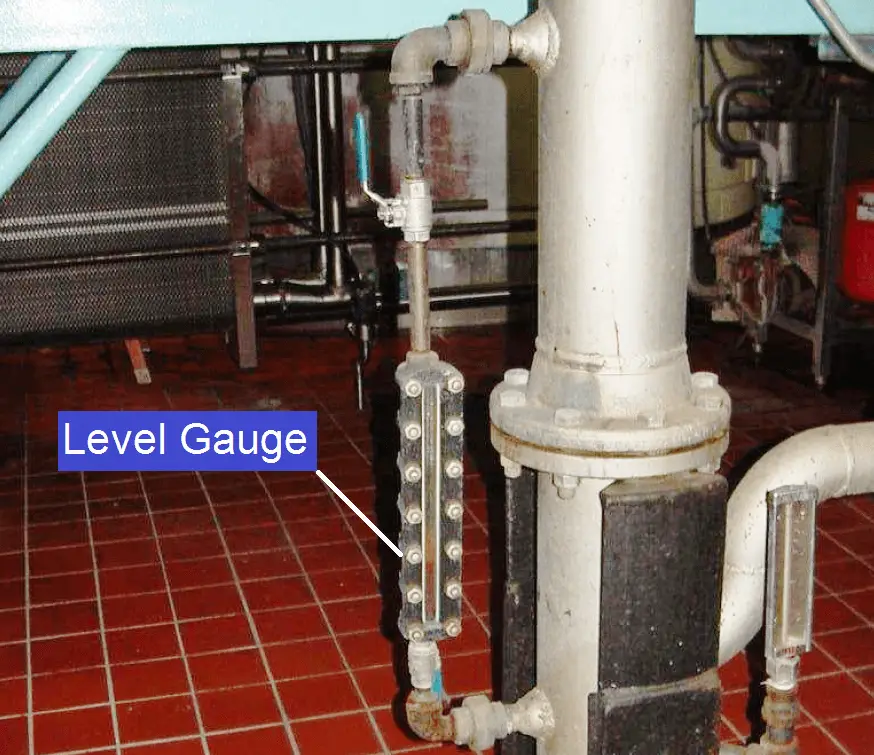
Level gauges are perhaps the simplest indicating instrument for liquid level in a vessel. They are often found in industrial level-measurement applications, even when another level-measuring instrument is present, to serve as a direct indicator for an operator to monitor in case there is doubt about the accuracy of the other instrument.
The level gauge, or sightglass is to liquid level measurement as manometers are to pressure measurement: a very simple and effective technology for direct visual indication of process level. In its simplest form, a level gauge is nothing more than a clear tube through which process liquid may be seen. The following photograph shows a simple example of a sightglass:

A functional diagram of a sightglass shows how it visually represents the level of liquid inside a vessel such as a storage tank:
A level gauge is not unlike a U-tube manometer, with equal pressures applied to both liquid columns (one column being the liquid in the gauge sightglass, the other column being the liquid in the vessel).
Level gauge valves exist to allow replacement of the glass tube without emptying or depressurizing the process vessel. These valves are usually equipped with flow-limiting devices in the event of a tube rupture, so too much process fluid does not escape even when the valves are fully open.
Some level gauges called reflex gauges are equipped with special optics to facilitate the viewing of clear liquids, which is problematic for simple glass-tube sightglasses.
A weakness of glass-tube level gauges is the glass tube itself. The tube must be kept in a clean condition in order for the liquid level to be clearly visible, which may be a problem in a dirty-liquid service. Also, glass tubes may rupture if subjected to thermal or mechanical shock. One solution to this problem is to eliminate the glass tube entirely, replacing it with a non-magnetic metal tube (e.g. stainless steel) containing a magnetized float, with magnet-sensing indicator flags outside of this tube to visually indicate level. Here is one example of such a level gauge :
In this instrument, you can see red-colored flags toward the bottom of the scale which have been “flipped” by the motion of the magnetic float inside the stainless-steel tube. The height of the red zone (i.e. how many flags have been flipped to show their red sides) indicates the height of the liquid inside the tube.
Some magnetic level gauges even have high- and low-level magnetic switches located at strategic points along the tube’s height, providing discrete sensing capability for alarms and/or shutdown controls, if the liquid level ever goes outside of safe operating limits. These switches will open and close as the magnetic float passes by, remotely signaling liquid level at that height.
Credits : Tony R. Kuphaldt – Creative Commons Attribution 4.0 License
The conveyor sorting machine is widely used in the packing industries using the PLC program…
Learn the example of flip-flop PLC program for lamps application using the ladder logic to…
In this article, you will learn the STAR DELTA programming using PLC controller to start…
Lube oil consoles of rotary equipment packages in industrial process plants are usually equipped with…
Rotating equipment packages such as pumps, compressors, turbines need the lube oil consoles for their…
This article explains how to blink lights in ladder logic with a detailed explanation video…