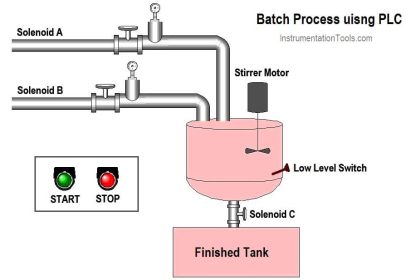
The most popular form of signal transmission used in modern industrial instrumentation systems is the 4 to 20 mA DC current signal.
This is an analog signal standard, meaning that the electric current is used to proportionately represent measurements or command signals.
Analog Signals
Typically, a 4 milliamp current value represents 0% of scale, a 20 milliamp current value represents 100% of scale, and any current value in between 4 and 20 milliamps represents a commensurate percentage in between 0% and 100%.
The following table shows the corresponding current and percentage values for each 25% increment between 0% and 100%. Every instrument technician tasked with maintaining 4-20 mA instruments commits these values to memory because they are referenced so often:

For example, if we were to calibrate a 4-20 mA temperature transmitter for a measurement range of 50 to 250 degrees C, we could relate the current and measured temperature values on a graph like this:

3 to 15 PSI and 4 to 20 mA
This is not unlike 3-15 pounds per square inch (PSI) pneumatic signal standard, where a varying air pressure signal proportionately represents some process variable.
Both 3-15 PSI and 4-20 mA signal standards are referred to as live zero because their ranges begin with a non-zero value. This “live” zero provides a simple means of discriminating between a legitimate 0% signal value and a failed signal (e.g. leaking tube or damaged cable)
An important concept with all analog instrumentation is that instruments sending and receiving analog signals must be compatibly ranged in order to properly represent the desired variable.
For example, let us consider a temperature measurement system consisting of a thermocouple, a temperature transmitter, a 250 ohm resistor (to convert the 4-20 mA analog signal into a 1-5 volt analog signal), and a special voltmeter functioning as a temperature indicator:
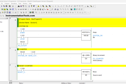
4 to 20 mA Signals

Note that how the output range of each sending device matches the input range of its corresponding receiving device. If we view this system as a path for information to flow from the thermocouple’s tip to the transmitter to the resistor and finally to the voltmeter/indicator, we see that the analog output range of each device must correspond to the analog input range of the next device, or else the real-world meaning of the analog signal will be lost.
This correspondence does not happen automatically but must be established by the instrument technician building the system. In this case, it would be the technician’s responsibility to properly adjust the range of the temperature transmitter, and also to ensure the indicator’s display scale was properly labeled.
Both the thermocouple and the resistor are non-adjustable devices, their input/output characteristics being fixed by physical laws.
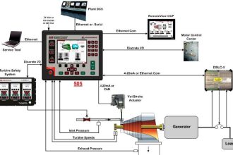
DC current signals are also used in control systems to command the positioning of a final control element, such as a control valve or a variable-speed motor drive (VSD).
In these cases, the milliamp value does not directly represent a process measurement, but rather how the degree to which the final control element influences the process.
Typically (but not always!), 4 milliamps commands a closed (shut) control valve or a stopped motor, while 20 milliamps commands a wide-open valve or a motor running at full speed.
Final control elements often are equipped with adjustable ranges so that an accurate correspondence between the analog signal and the desired control action may be ensured.

Thus, most industrial control systems use at least two different 4-20 mA signals: one to represent the process variable (PV) and one to represent the command signal to the final control element (the “manipulated variable” or MV):
The relationship between these two signals depends entirely on the response of the controller. There is no reason to ever expect the PV and MV current signals to be equal to each other, for they represent entirely different variables.
In fact, if the controller is reverse-acting, it is entirely normal for the two current signals to be inversely related: as the PV signal increases going to a reverse-acting controller, the output signal will decrease.
If the controller is placed into “manual” mode by a human operator, the output signal will have no automatic relation to the PV signal at all, instead being entirely determined by the operator.
Also Read: Standard 4-20mA Conversion Formula
If you liked this article, then please subscribe to our YouTube Channel for PLC and SCADA video tutorials.
You can also follow us on Facebook and Twitter to receive daily updates.
Read Next:


Thank you sir for the information.
Very Good information on 4-20mA current signals.
Thank you for this information. I have always wanted to understand 4-20mA signal, but now I have understood it with your help
Dear sir,
please tell me about why we short the two wires of RTD and one common in three core wire RTD.and show the formula for how we can convert the resistance into temperature.
In the field, for non 4-20mA instruments, how can you tell if they are analog or discreet?
Thank you sir…
Thank u sir….
Muito obrigado pelo artigo!
Thank you sir
it is very useful for me to learn what is 4-20mA current signals.
Very clear. Thank you.
THANK YOU SIR