An analyzer measures intrinsic properties of a substance sample such as its density, chemical content, or purity. Whereas the other types of instruments discussed in this chapter measure quantities incidental to the composition of a substance (pressure, level, temperature, and flow rate), an analyzer measures something related to the nature of substance being processed.
To calibrate an instrument means to check and adjust (if necessary) its response so the output accurately corresponds to its input throughout a specified range. In order to do this, one must expose the instrument to an actual input stimulus of precisely known quantity. This is no different for an analytical instrument. In order to calibrate an analyzer, we must exposed it to known quantities of substances with the desired physical and/or chemical properties (density, chemical composition, etc.). In other words, we need to use chemical standards.
A classic example of this is the calibration of a pH analyzer. pH is the measurement of hydrogen ion activity in an aqueous solution. The standard range of measurement is 0 pH to 14 pH, the number representing a negative power of 10 approximately describing the hydrogen ion molarity of the solution (how many moles of active hydrogen ions per liter of solution).
The pH of a solution is typically measured with a pair of special electrodes immersed in the solution, which generate a voltage proportional to the pH of the solution. In order to calibrate a pH instrument, you must have a sample of liquid solution with a known pH value. For pH instrumentation, such calibration solutions are called buffers, because they are specially formulated to maintain stable pH values even in the face of (slight levels of) contamination.
pH buffers may be purchased in liquid form or in powder form. Liquid buffer solutions may be used directly out of the bottle, while powdered buffers must be dissolved in appropriate quantities of de-ionized water to generate a solution ready for calibration use. Pre-mixed liquid buffers are convenient to use, but have a fairly limited shelf life. Powdered buffer capsules are generally superior for long-term storage, and also enjoy the advantage of occupying less storage space in their dry state than a liquid buffer solution.
The following photograph shows a few 7.00 pH (± 0.02 pH) buffer capsules ready to be mixed with water to form a usable buffer solution:
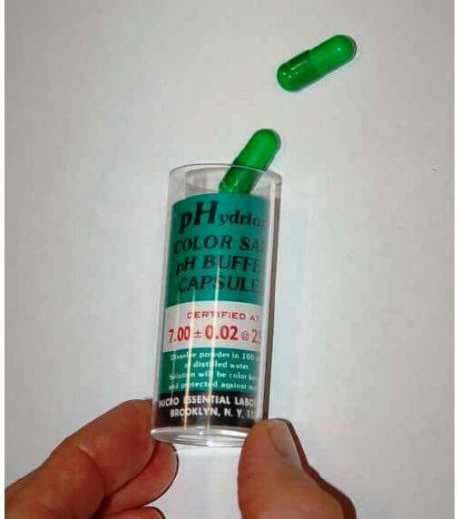
After preparing the buffer solution in a cup, the pH probe is inserted into the buffer solution and given time to stabilize. One stabilized, the pH instrument may be adjusted to register the proper pH value. Buffer solutions should not be exposed to ambient air for any longer than necessary (especially alkaline buffers such as 10.0 pH) due to contamination. Pre-mixed liquid buffer storage containers should be capped immediately after pouring into working cups. Used buffer solution should be discarded rather than re-used at a later date.
Analyzers designed to measure the concentration of certain gases in air must be calibrated in a similar manner. Oxygen analyzers, for example, used to measure the concentration of free oxygen in the exhaust gases of furnaces, engines, and other combustion processes must be calibrated against known standards of oxygen concentration. An oxygen analyzer designed to measure oxygen concentration over a range of ambient (20.9% oxygen) to 0% oxygen may be calibrated with ambient air as one of the standard values, and a sample of pure nitrogen gas (containing 0% oxygen) as the other standard value. An oxygen analyzer intended for the measurement of oxygen concentrations in excess of ambient air would require a different standard, most likely a sample of 100% pure oxygen, as a calibration reference.
An analyzer designed to measure the concentration of hydrogen sulfide (H2S), a toxic gas produced by anaerobic bacterial decomposition of organic matter, will require a sample of gas with a precisely known concentration of hydrogen sulfide mixed in it as a calibration reference. A typical reference gas concentration might be 25 or 50 parts per million (ppm). Gas mixtures with such precise concentration values as this may be purchased from chemical laboratories for the purpose of calibrating concentration analyzers, and are often referred to as span gases because they are used to set the span of analyzer instruments.
Analytical instruments are generally subject to greater drifting over time than instruments that measure incidental quantities such as pressure, level, temperature, or flow rate. It is not uncommon for instrument technicians to be tasked with daily calibration checks of certain instruments responsible for monitoring atmospheric or water emissions at industrial facilities. For this reason, it is often practical to equip such critical analyzers with self-calibration systems. A self-calibration system is a system of solenoid (electrically controlled on-off) valves and reference gas bottles set up in such a way that a computer is able to switch the analyzer off-line and subject it to standard reference gases on a regular schedule to check calibration. Many analyzers are programmed to automatically calibrate themselves against these reference gases, thus eliminating tedious work for the instrument technician.
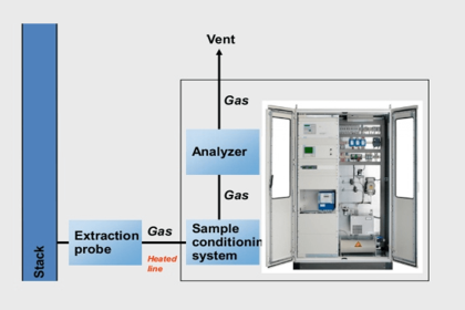
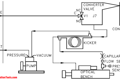
A typical self-calibration system for a gas analyzer might look like this:
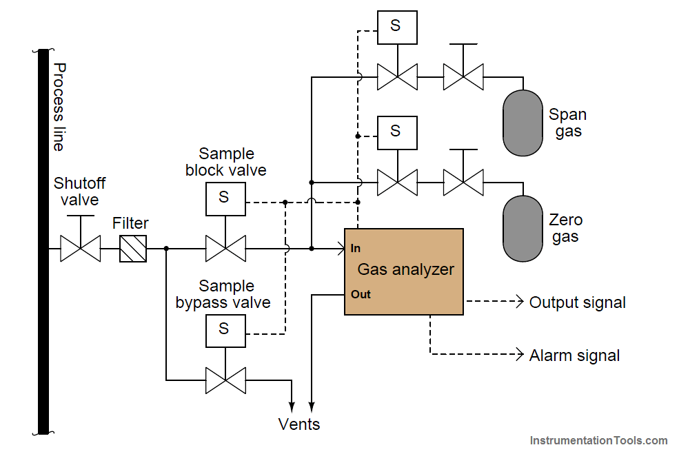
The gas analyzer is equipped with its own auto-calibration controls and programming, allowing it to periodically shut off the process sample and switch to known reference gases for “zero” and “span” calibration checks. If these checks indicate excessive drift or any other questionable results, the analyzer has the ability to flag a maintenance alarm to alert an instrument technician to a potential problem that may require servicing. This sort of self-calibration and self-diagnostic capability saves the instrument technician from having to spend substantial time running manual calibration checks, yet alerts the technician if anything is in need of actual repair. Barring any component failures within this system, the only maintenance this system will need is periodic replacement of the calibration gas bottles.