Air to open/close valves and direction of control action
Control valves come in two sorts: air to open; and air to close.
Air to open valves are normally held closed by the spring and require air pressure (a control signal) to open them – they open progressively as the air pressure increases.
Air to close valves are valves which are held open by the valve spring and require air pressure to move them towards the closed position.
The reason for the two types of valves is to allow fail safe operation. In the event of a plant instrument air failure it is important that all control valves fail in a safe position (e.g. an exothermic reactor’s feed valves (or, perhaps, just one of the valves) should fail closed (air to open) and its coolant system valves fail open (air to close)).
The type of valve used obviously impacts on what a controller has to do – changing the type of valve would mean that the controller would need to move the manipulation in the opposite direction.
To simplify things in this course we shall assume that we are always using air to open valves – an increase in control action will cause the valve to open and the flow through it to increase.
The other important thing you need to understand is the direction of control action. Consider the system shown in the diagram.
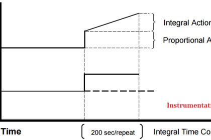
PID Controller Action

Consider Two cases :
1) Level Controller LC controlling discharge control valve.
In this process I have connected a level controller to the bottom valve. For this configuration the controller needs to increase its signal (and hence the flow) when the level in the tank increases.
2) Level Controller LC controlling inlet control valve.
In this case the controller needs to reduce the flow when the level in the tank increases.
Both configurations are equally capable of controlling the level, but they require the controller to do entirely opposite things. This is what direction of control action involves.
A direct acting controller is one whose output tends to increase as the measurement signal increases.
A reverse acting controller is one whose output tends to decrease as the measurement signal increases.
All control systems are programmable (usually marked DIR/REV) which allows the controller to be switched from direct acting to reverse acting or vice versa.
It is important to get the correct direction of control action. If things are set-up correctly a feedback control system will experience negative feedback, which means that the system will act to reduce errors in its output.
If you get the direction of control action wrong the system will undergo positive feedback and will act to reinforce output errors – this is very likely to cause the system to go unstable. If you are having problems in setting up a stable controller the first thing to check is that you have set the correct direction of control action!
Different Combinations of Control Valves & Controllers action
1. Fail Open Control Valve / Direct Acting Controller
If a fail open control valve is paired with a direct acting controller we get the following process performance: On rising process level the controller output rises which closes the valve.
If the process level is below the set point the controller would be wide open.
This would behave similar to a direct acting regulator only the valve / controller response is slower.
2.Fail Open Control Valve / Reverse Acting Controller
In this case when the process level rises the controller output decreases which tends to open the valve.
If the process level is below the set point the valve is closed.
An example of this application is a compressor recycle valve.
3.Fail Closed Control Valve / Direct Acting Controller
This is the same as the fail open valve / reverse acting controller. An increase in process level means an increase in controller output which means the valve is opened.
If the process level is below the set point the valve is closed. A typical application is backpressure control. (In this case the valve controller acts similar to that of a PSV.)
4.Fail Closed Control Valve / Reverse Acting Controller
A rise in process level means a decrease in controller output which means the valve is closed.
If the process level is below the set point the valve is open.
This is typically used for pressure control.
Also Read: Air Filter Regulator Working Animation