This article will discuss the Automatic Vehicle entry-exit tracking and Parking System using Omron PLC CX-Programmer. The system is designed to manage parking areas that can operate automatically or manually. In manual mode, the operator can control the Gate Open/Close process using buttons. The PLC system will detect the presence of vehicles entering or exiting, record the number of vehicles, and limit parking capacity. This system can provide an indicator if the parking area is full or there are available parking slots.
Program Objective
System Sequence
- Initialization:
- The system starts by setting the parking area capacity to “50” slots.
- The system is in Standby mode.
- Vehicle Entry Process:
- A vehicle approaches the entrance Gate, and the entry sensor detects it.
- If parking slots are available, the Green lamp indicator turn On, the Gate automatically Opens, the vehicle enters, and the system increments the Counter by “1”.
- If the parking is full, the Gate remains Closed, and the Red lamp indicator turn On.
- Vehicle Exit Process:
- A vehicle approaches the exit gate, and the exit sensor detects it.
- The Gate automatically Opens, the vehicle exits, and the system decrements the Counter by “1”.
- Capacity Management:
- The system ensures the number of vehicles in the parking area does not exceed the maximum capacity.
- If the parking is full, the entrance Gate will Not Open until a vehicle exits.
- Manual Mode:
- In manual mode, the Gate can be operated using the UP/Down buttons.
- Alarm and Indicators:
- The Green lamp indicator turn On if there are available parking slots.
- The Red lamp indicator turn On if the parking is full.
IO Mapping
| S.No. | Comment | Input (I) | Output (Q) | Memory Bit | Memory Word |
|---|---|---|---|---|---|
| 1 | PB_START | 0.00 | |||
| 2 | PB_STOP | 0.01 | |||
| 3 | AUTO/MANUAL | 0.02 | |||
| 4 | PB_UP | 0.03 | |||
| 5 | LS_HIGH | 0.04 | |||
| 6 | PB_DOWN | 0.05 | |||
| 7 | LS_LOW | 0.06 | |||
| 8 | SENS_CAR_1 | 0.07 | |||
| 9 | SENS_CAR_2 | 1.00 | |||
| 10 | RESET_COUNTER | 1.01 | |||
| 11 | GATE_UP | 100.00 | |||
| 12 | GATE_DOWN | 100.01 | |||
| 13 | LAMP_GREEN | 100.02 | |||
| 14 | LAMP_RED | 100.03 | |||
| 15 | CAR_COUNT | D0 | |||
| 16 | SYSTEM_ON | W0.00 | |||
| 17 | GATE_UP_MANUAL | W0.01 | |||
| 18 | GATE_DOWN_MANUAL | W0.02 | |||
| 19 | GATE_UP_AUTO_IN | W0.03 | |||
| 20 | GATE_DOWN_AUTO_IN | W0.04 | |||
| 21 | GATE_UP_AUTO_OUT | W0.05 | |||
| 22 | GATE_DOWN_AUTO_OUT | W0.06 | |||
| 23 | INTERLOCK_CAR_IN | W0.07 | |||
| 24 | INTERLOCK_CAR_OUT | W0.08 |
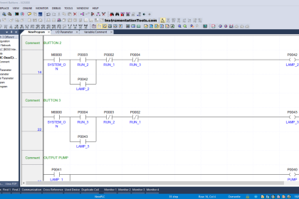
Vehicle Entry-Exit Tracking System
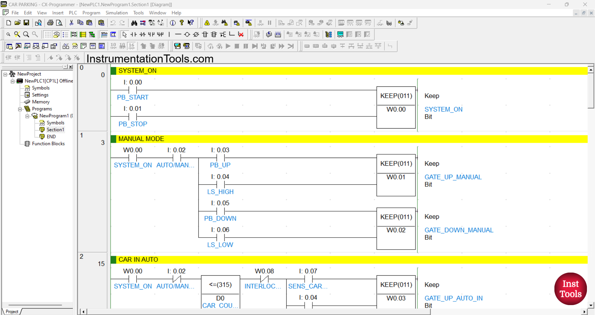
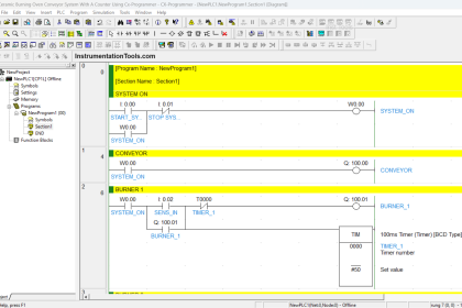
RUNG 0 (SYSTEM ON)
In this Rung, the memory bit SYSTEM_ON (W0.00) will be in the HIGH state when the PB_START (0.00) button is Pressed. Because it uses the KEEP(011) instruction, the memory bit SYSTEM_ON (W0.00) will remain in the HIGH state even though the PB_START (0.00) button has been Released.
The memory bit SYSTEM_ON (W0.00) will be in the LOW state if the PB_STOP (0.01) button is Pressed.
RUNG 1 (MANUAL MODE)
In this Rung, the memory bit SYSTEM_ON (W0.00) will be in the HIGH state when the NO contact of the memory bit SYSTEM_ON (W0.00) and the AUTO/MANUAL (0.02) Selector Switch are in the HIGH state and the PB_UP (0.03) button has been Pressed.
The memory bit GATE_UP_MANUAL (W0.01) will be in the LOW state if the Limit Switch LS_HIGH (0.04) is in the HIGH state.
The memory bit GATE_DOWN_MANUAL (W0.02) will be in the HIGH state when the NO contact of the memory bit SYSTEM_ON (W0.00) and the AUTO/MANUAL (0.02) Selector Switch are in the HIGH state and the PB_DOWN (0.05) button has been Pressed.
The memory bit GATE_DOWN_MANUAL (W0.02) will be in the LOW state if the Limit Switch LS_LOW (0.06) is in the HIGH state.
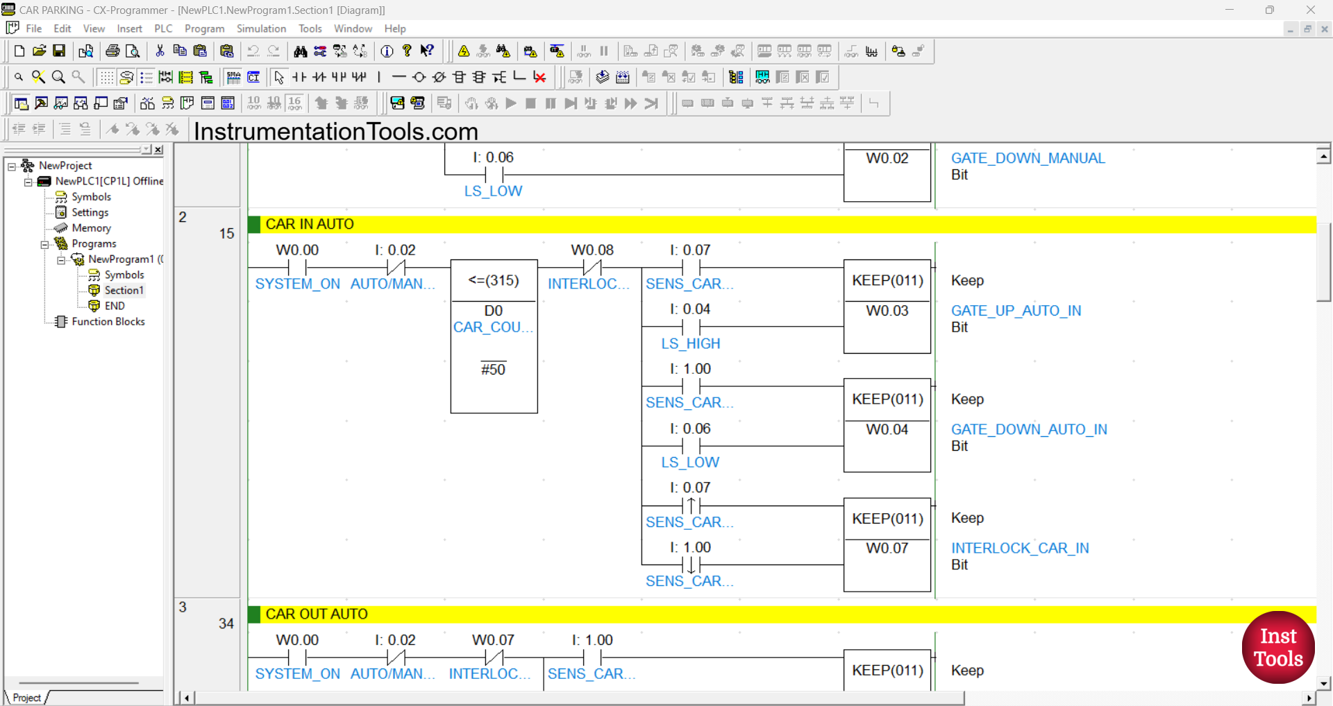
RUNG 2 (CAR IN AUTO)
In this Rung, the memory bits GATE_UP_AUTO_IN (W0.03) and INTERLOCK_CAR_IN (W0.07) will be in the HIGH state when the NO contacts of the memory bit SYSTEM_ON (W0.00) and Sensor SENS_CAR_1 (0.07) are in the HIGH state and the value of the memory word CAR_COUNT (D0) Less Than Or Equal To “50”.
The memory bit GATE_UP_AUTO_IN (W0.03) will be in the LOW state when the NO contact of the limit switch LS_HIGH (0.04) is in the HIGH state.
The memory bit GATE_DOWN_AUTO_IN (W0.04) will be in the HIGH state when the NO contact of the memory bit SYSTEM_ON (W0.00) and Sensor SENS_CAR_2 (1.00) are in the HIGH state and the value of the memory word CAR_COUNT (D0) is Less Than Or Equal “50”.
The memory bit GATE_DOWN_AUTO_IN (W0.04) will be in the LOW state when the NO contact of the limit switch LS_LOW (0.06) is in the HIGH state.
The memory bit INTERLOCK_CAR_IN (W0.07) will be in the LOW state when the NO contact of the sensor SENS_CAR_2 (1.00) changes to the LOW state.
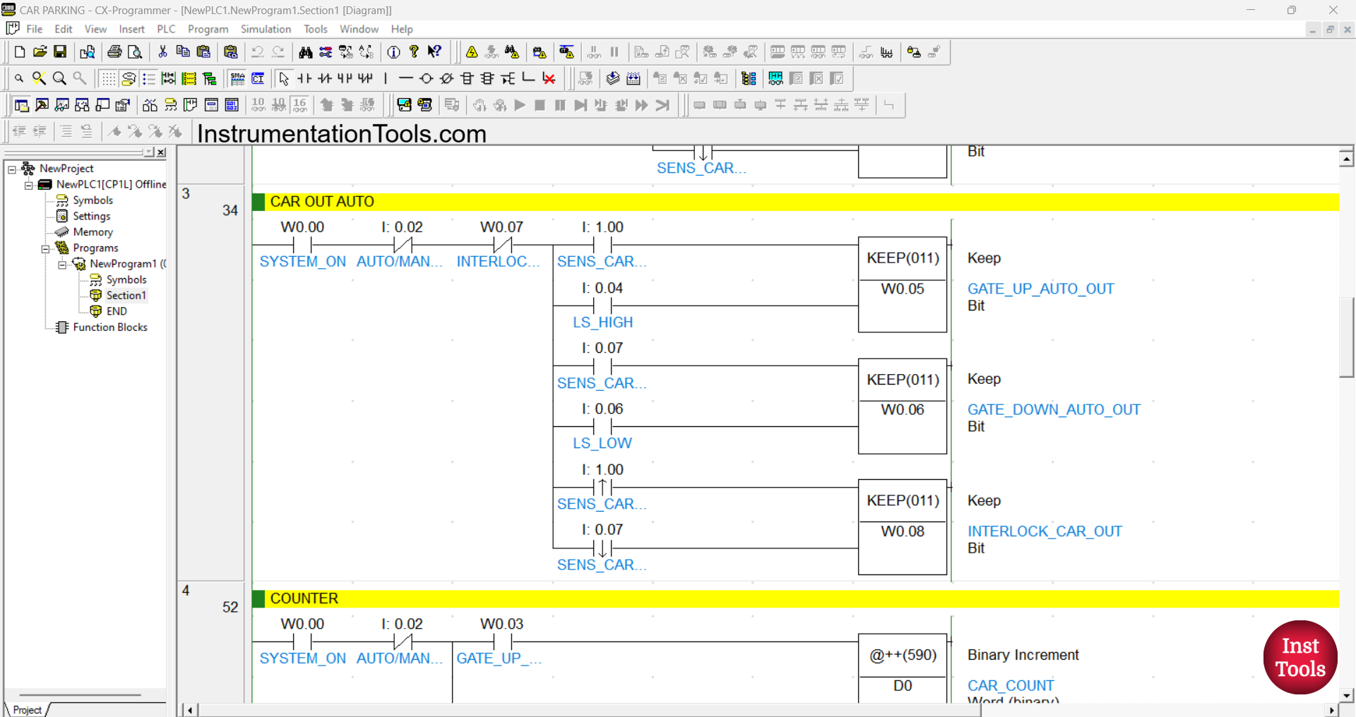
RUNG 3 (CAR OUT AUTO)
In this Rung, the memory bits GATE_UP_AUTO_OUT (W0.05) and INTERLOCK_CAR_OUT (W0.08) will be in the HIGH state when the NO contacts of the memory bit SYSTEM_ON (W0.00) and Sensor SENS_CAR_2 (1.00) are in the HIGH state.
The memory bit GATE_UP_AUTO_OUT (W0.05) will be in the LOW state when the NO contact of the limit switch LS_HIGH (0.04) is in the HIGH state.
The memory bit GATE_DOWN_AUTO_OUT (W0.06) will be in the HIGH state when the NO contacts of the memory bit SYSTEM_ON (W0.00) and Sensor SENS_CAR_1 (0.07) are in the HIGH state.
The memory bit GATE_DOWN_AUTO_OUT (W0.06) will be in the LOW state when the NO contact of the limit switch LS_LOW (0.06) is in the HIGH state.
The memory bit INTERLOCK_CAR_OUT (W0.08) will be in the LOW state when the NO contact of the sensor SENS_CAR_1 (0.07) changes to the LOW state.
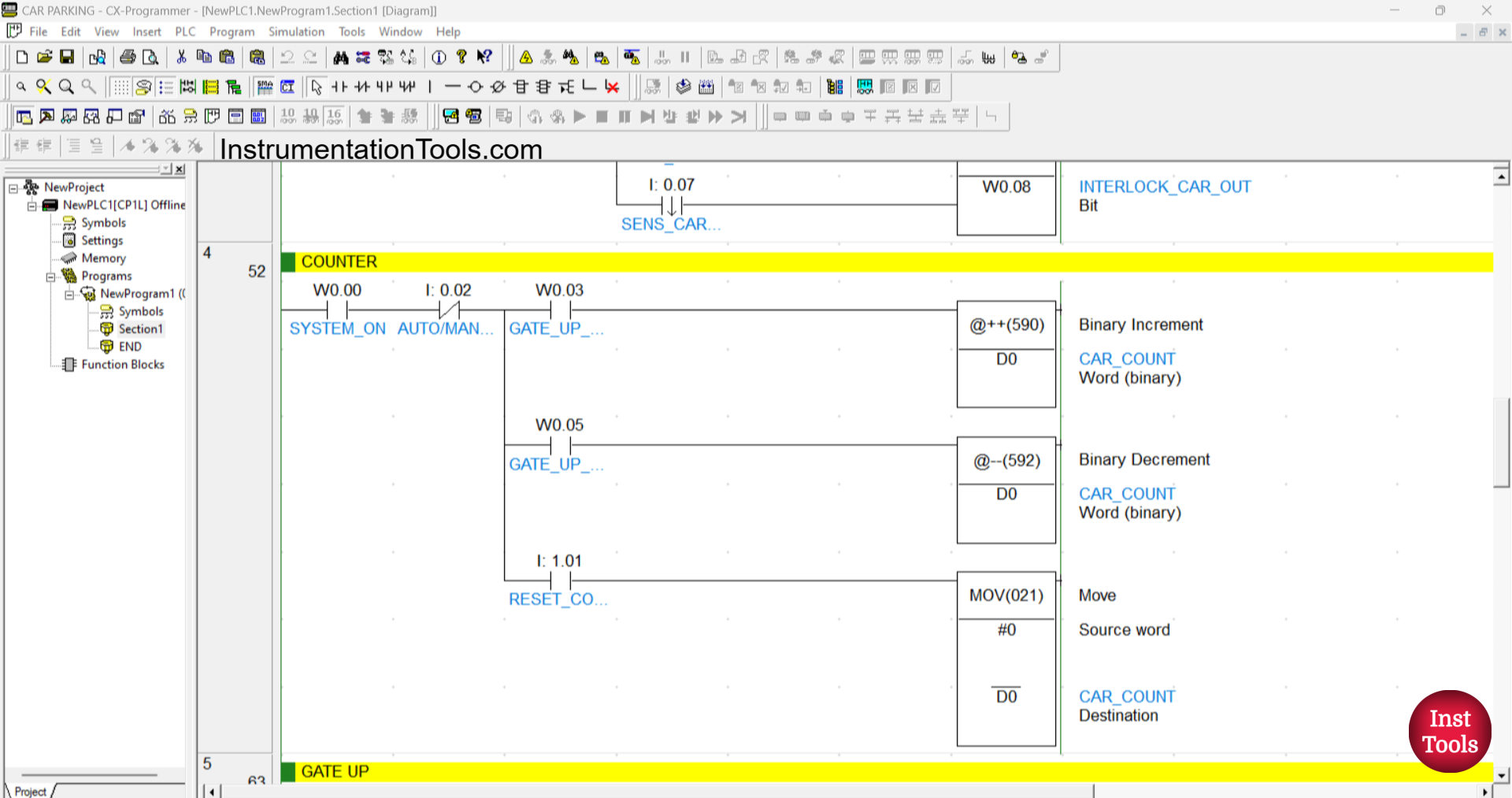
RUNG 4 (COUNTER)
In this rung, when the NO contacts of the memory bits SYSTEM_ON (W0.00) and GATE_UP_AUTO_IN (W0.03) are in the HIGH state, the value in the memory word CAR_COUNT (D0) will increase (+1).
And when the NO contacts of the memory bits SYSTEM_ON (W0.00) and GATE_UP_AUTO_OUT (W0.05) are in the HIGH state, the value in the memory word CAR_COUNT (D0) will decrease (-1).
If, when the NO contact of the memory bit SYSTEM_ON (W0.00) is in the HIGH state, and the RESET_COUNTER (1.01) button is Pressed, then the value in the memory word CAR_COUNT (D0) will be reset to zero value “0”.
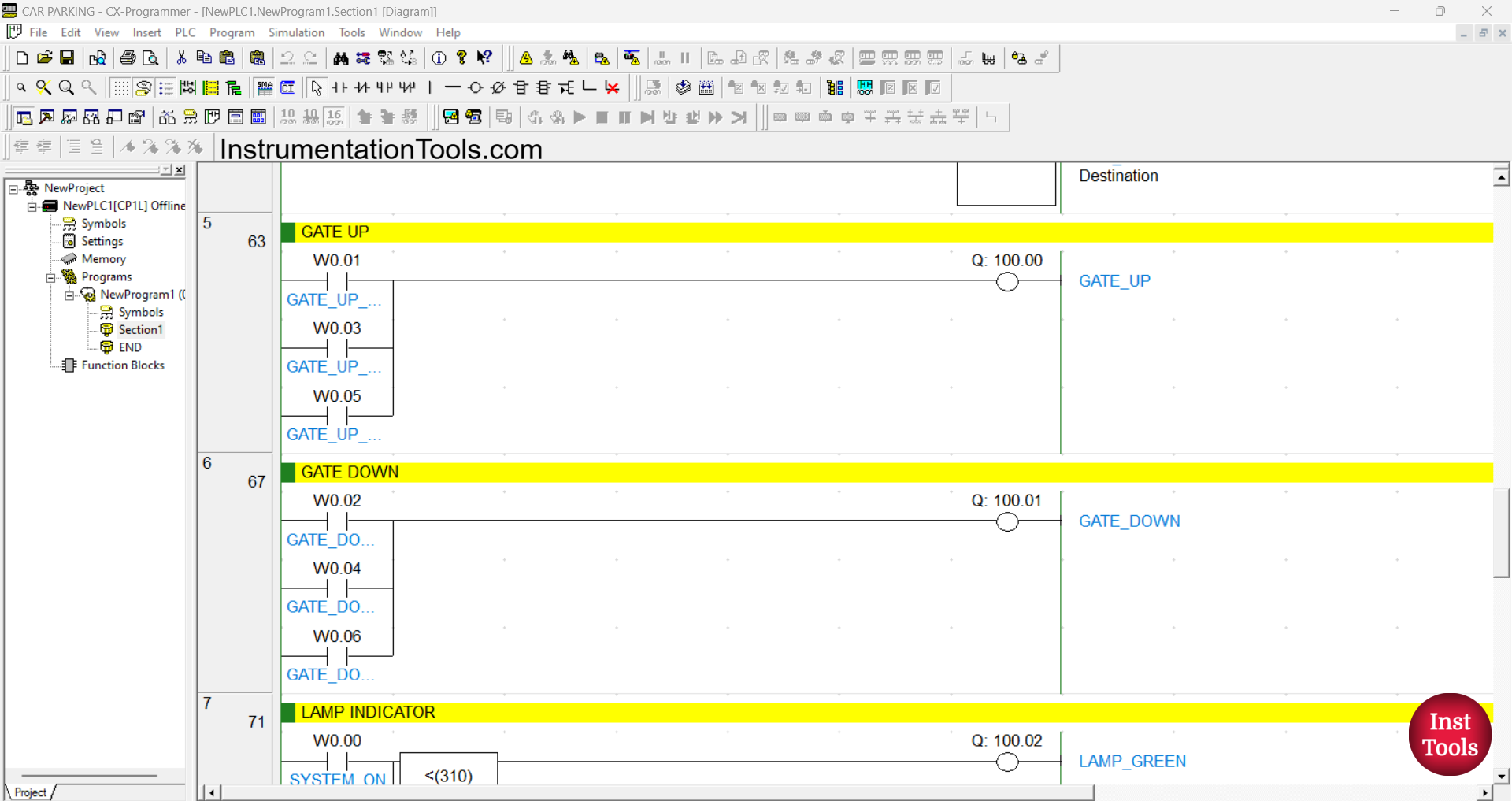
RUNG 5 (GATE UP)
In this Rung, when the NO contact of the memory bits GATE_UP_MANUAL (W0.01) or GATE_UP_AUTO_IN (W0.03) or GATE_UP_AUTO_OUT (W0.05) is in the HIGH state, the GATE_UP (100.00) output will be ON.
RUNG 6 (GATE DOWN)
In this Rung, when the NO contact of the memory bits GATE_DOWN_MANUAL (W0.02) or GATE_DOWN_AUTO_IN (W0.04) or GATE_DOWN_AUTO_OUT (W0.06) is in the HIGH state, the GATE_DOWN (100.01) output will be ON.
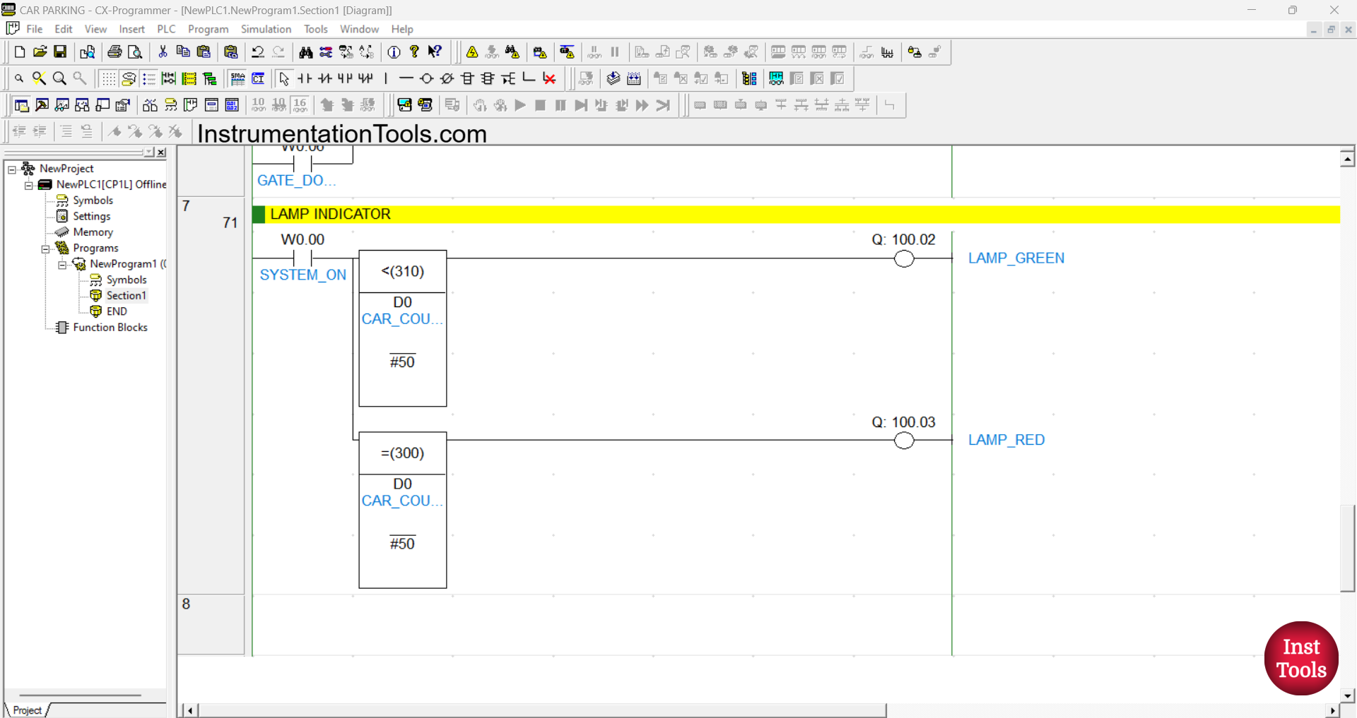
RUNG 7 (LAMP INDICATOR)
In this Rung, the output LAMP_GREEN (100.02) will be ON when the NO contact of the memory bit SYSTEM_ON (W0.00) and the value of the memory word CAR_COUNT (D0) is Less Than “50”.
The output LAMP_RED (100.03) will be ON when the NO contact of the memory bit SYSTEM_ON (W0.00) and the value of the memory word CAR_COUNT (D0) is Equal To “50”.
Read Next:
- How to Use Analog Output in Mitsubishi FX3U PLC?
- Mitsubishi PLC – Convert Integer to Float in Ladder Logic
- Mitsubishi PLC + Weintek HMI: Analog Output Demo
- Analog Voltage Control in PLC Using Weintek HMI MT6071IE
- Scaling Analog Input to 0-100% in Mitsubishi FX3U PLC