This article discusses an example of a gas monitoring logic based on alarm level indicators using a Siemens PLC. The PLC system functions to detect gas concentration in a room and provide an automatic safety response. It classifies gas status into three levels: Normal (safe condition), Medium (early warning), and Hazardous (emergency action), with different responses at each level, such as alarms, indicator lights, or exhaust fan activation. By utilizing real-time sensor data comparison, the system can make independent decisions.
Program Objective
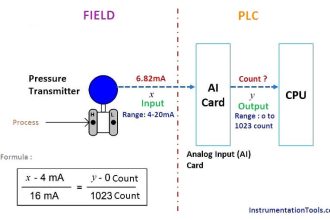
Gas Detection System Process
1. Three Levels of Gas Detection:
- Normal: Safe gas levels.
- Medium: Gas levels are increasing and require attention.
- Danger: Critical gas levels with potential hazards.
2. Alarm & Visual Indicators:
Each level has different indicator lights and automatic actions.
3. Flexible Settings:
Adjustable Setpoints: The threshold values for each level can be customized as needed.
System Response at Each Level:
- Normal Level (Green):
- The green light is on.
- The exhaust fan is off.
- The environment is safe.
- Medium Level (Orange):
- The orange light is on.
- The exhaust fan is activated to reduce gas concentration.
- Danger Level (Red):
- The red light is on.
- The exhaust fan is activated.
- Water sprinklers automatically turn on to neutralize hazardous gases.
IO Mapping
| S.No. | Comment | Input (I) | Output (Q) | Memory Bit | Memory Word |
|---|---|---|---|---|---|
| 1 | START | I0.0 | |||
| 2 | STOP | I0.1 | |||
| 3 | GREEN_LAMP | Q0.0 | |||
| 4 | ORANGE_LAMP | Q0.1 | |||
| 5 | RED_LAMP | Q0.2 | |||
| 6 | EXHAUST_FAN | Q0.3 | |||
| 7 | SPRINKLE | Q0.4 | |||
| 8 | PV_GAS | MW0 | |||
| 9 | SV_NORMAL | MW2 | |||
| 10 | SV_MEDIUM | MW4 | |||
| 11 | SV_DANGER | MW6 | |||
| 12 | SYSTEM_ON | M10.0 |
Gas Monitoring Logic

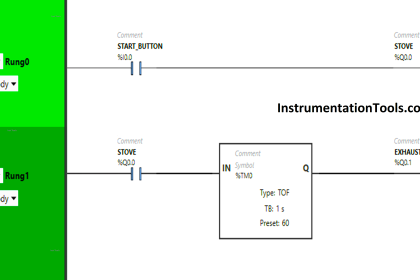
NETWORK 1 (START SYSTEM)
In this Network, the memory bit SYSTEM_ON (M10.0) will be in a HIGH state if the START(I0.0) button is pressed. The memory bit SYSTEM_ON (M10.0) will remain in a HIGH state even though the PB_START (I0.0) button has been released, because it uses Latching.
If the STOP (I0.1) button is pressed, the memory bit SYSTEM_ON (M10.0) will return to a LOW state.
NETWORK 2 (NORMAL LEVEL)
In this Network, the GREEN_LAMP (Q0.0) output will be ON if the NO contact of the memory bit SYSTEM_ON (M10.0) is in a HIGH state and the value in the memory words PV_GAS (MW0) is Less Than Or Equal To SV_NORMAL (MW2).
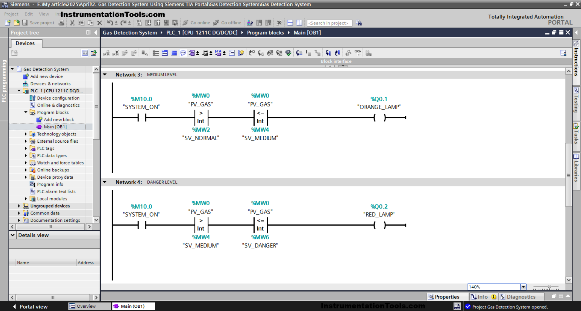
NETWORK 3 (MEDIUM LEVEL)
The ORANGE_LAMP(Q0.1) output will be ON if the NO contact of the memory bit SYSTEM_ON (M10.0) is in HIGH state and the value in the memory words PV_GAS (MW0) is Greater than SV_NORMAL (MW2) and Less Than or Equal to SV_MEDIUM (MW4).
NETWORK 4 (DANGER LEVEL)
The RED_LAMP (Q0.2) output will be ON if the NO contact of the memory bit SYSTEM_ON (M10.0) is in HIGH state and the value in the memory words PV_GAS (MW0) is Greater Than SV_MEDIUM (MW4) and Less Than or Equal to SV_DANGER (MW6).

NETWORK 5 (EXHAUST FAN)
In this Network, the EXHAUST_FAN (Q0.3) output will be ON when the NO contact of the memory bit SYSTEM_ON (M10.0) and either the NO contact of ORANGE_LAMP (Q0.1) or RED_LAMP (Q0.2) are in a HIGH state.
NETWORK 6 (SPRINKLE WATER)
In this Network, the SPRINKLE (Q0.4) output will be ON when the NO contact of the memory bit SYSTEM_ON (M10.0) and RED_LAMP(Q0.2) are in a HIGH state.
Read Next:
- Free Download ISPSoft Delta PLC Program Software
- Assigning Custom Keyboard Controls in FactoryTalk
- Compare Earth Resistance and Insulation Resistance
- Why is Control Valve Output Velocity Important?
- FactoryTalk SCADA Faceplates with Parameter Passing