This article will discuss PLC programming for a batch mixing system on 4 tanks using XG5000 software. This system will control the dosing of 3 liquid raw materials with different weights, then mix them into one tank for 10 seconds before flowing out.
Program Objective

This system has 4 Tanks and can only be started when Tank 4 is empty.
When the system has started, at the same time:
- Raw material-X will be flowed into Tank-1, and the filling process will stop when the liquid content has reached 25 liters.
- Raw material-Y will be flowed into Tank-2, and the filling process will stop when the liquid content has reached 20 liters.
- Z-raw materials will be flowed into Tank-3, and the filling process will stop when the liquid content has reached 30 liters.
After the process of filling X, Y, and Z raw materials is complete, all raw materials will be transferred into Tank-4. In this process, the valve will open for 10 seconds.
Next, in Tank-4, the Mixing Process will be carried out by rotating the Mixer Agitator for 10 seconds.
When the mixing process is complete, the mixed liquid will flow out of Tank-4.
The system can be started again after Tank-4 is empty.
Mix 3 Raw Materials in 4 Tanks
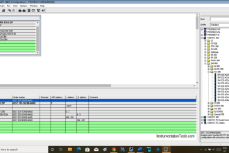
IO Mapping
| S.No. | Comment | Input (I) | Output (Q) | Memory Word | Memory Bits | Timer |
|---|---|---|---|---|---|---|
| 1 | PB_START | P0000 | ||||
| 2 | PB_STOP | P0001 | ||||
| 3 | VALVE_X | P0040 | ||||
| 4 | VALVE_Y | P0041 | ||||
| 5 | VALVE_Z | P0042 | ||||
| 6 | VALVE_OUT_XYZ | P0043 | ||||
| 7 | MIXER | P0044 | ||||
| 8 | VALVE_DRAIN | P0045 | ||||
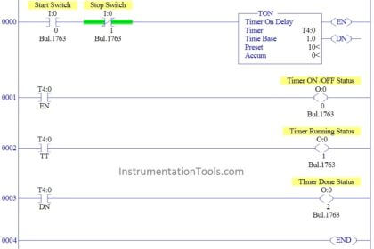
| 9 | TIMER1 | T000 | ||||
| 10 | TIMER_MIX | T001 | ||||
| 11 | SYSTEM_ON | M0000 | ||||
| 12 | IR_CUTOFF_X | M0001 | ||||
| 13 | IR_CUTOFF_Y | M0002 | ||||
| 14 | IR_CUTOFF_Z | M0003 | ||||
| 15 | IR_CUTOFF_DRAIN | M0004 | ||||
| 16 | PV_TANK_1 | D0000 | ||||
| 17 | PV_TANK_2 | D0001 | ||||
| 18 | PV_TANK_3 | D0002 | ||||
| 19 | PV_TANK_4 | D0003 |
PLC Logic Explained

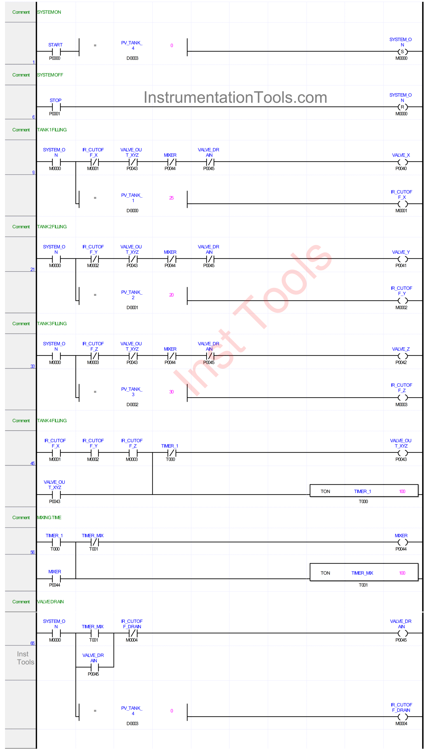
RUNG 1 (SYSTEM ON)
In this Rung, if the PB_START (P0000) button is pressed and the value in memory word PV_TANK_4 (D3) is Equal To Zero “0”, then the memory bit SYSTEM_ON (M0000) will be in HIGH state. The memory bit SYSTEM_ON (M0000) will remain in HIGH state even though the PB_START (P0000) button has been released, because it uses the SET Coil Instruction.
RUNG 6 (SYSTEM OFF)
In this Rung, because it uses the RESET Coil Instruction, the memory bit SYSTEM_ON (M0000) will return to the LOW state if the PB_STOP (P0001) button is pressed.
RUNG 9 (TANK 1 FILLING)
The output VALVE_X (P0040) will be OPEN if the NO contact of memory bit SYSTEM_ON (M0000) is in the HIGH state. The memory bit IR_CUTOFF_X (M0001) will be in the HIGH state when the value in memory word PV_TANK_1 (D0000) is Equal To “25”.
Output VALVE_X (P0040) will be CLOSED if one of the NC contacts of memory bit IR_CUTOFF_X(M0001) or Output VALVE_OUT_XYZ (P0043), MIXER (P0044), and VALVE_DRAIN (P0045) is in the HIGH state.

RUNG 21 (TANK 2 FILLING)
The output VALVE_Y (P0041) will be OPEN when the NO contact of memory bit SYSTEM_ON (M0000) is in the HIGH state. And the memory bit IR_CUTOFF_Y (M0002) will be in the HIGH state if the value in memory word PV_TANK_2 (D0001) is Equal To “20”.
Output VALVE_Y (P0041) will be CLOSED if one of the NC contacts of memory bit IR_CUTOFF_Y (M0002) or Output VALVE_OUT_XYZ (P0043), MIXER (P0044), and VALVE_DRAIN (P0045) is in the HIGH state.
RUNG 33 (TANK 3 FILLING)
The output VALVE_Z (P0042) will be OPEN when the NO contact of memory bit SYSTEM_ON (M0000) is in the HIGH state. And the memory bit IR_CUTOFF_Z (M0003) will be in the HIGH state if the value in the memory word PV_TANK_3 (D0002) is Equal To “30”.
Output VALVE_Z (P0042) will be CLOSED if one of the NC contacts of memory bit IR_CUTOFF_Z (M0003) or Output VALVE_OUT_XYZ (P0043), MIXER (P0044), and VALVE_DRAIN (P0045) is in the HIGH state.
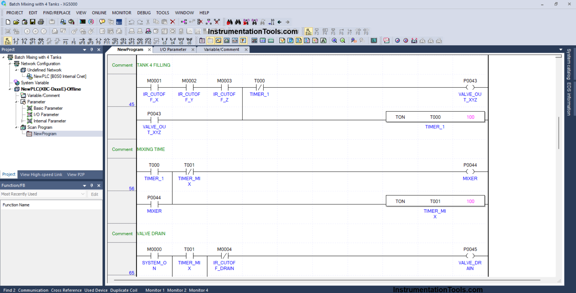
RUNG 45 (TANK 4 FILLING)
The output VALVE_OUT_XYZ (P0043) will be OPEN when the NO contacts of memory bits IR_CUTOFF_X (M0001), IR_CUTOFF_Y (M0002), and IR_CUTOFF_Z (M0003) are in the HIGH state.
Timer TIMER1 (T000) will start counting up to “10” seconds, and if Timer TIMER1 (T000) has finished counting, then the output VALVE_OUT_XYZ (P0043) will CLOSE.
RUNG 56 (MIXING TIME)
In this Rung, the output MIXER (P0044) will be ON when the NO contact of Timer TIMER1 (T000) is in the HIGH state.
The TIMER_MIX (T001) timer will start counting up to “10” seconds, and when the TIMER_MIX (T001) timer has finished counting, the output MIXER (P0044) will turn OFF.

RUNG 65 (VALVE DRAIN)
In this Rung, the output VALVE_DRAIN (P0045) will be OPEN when the NO contact of memory bit SYSTEM_ON (M0000) and Timer TIMER_MIX (T001) are in the HIGH state.
When the value in memory word PV_TANK_4 (D0003) is Equal To Zero “0”, then the memory bit IR_CUTOFF_DRAIN (M0004) will be in the HIGH state, and the output VALVE_DRAIN (P0045) will return to CLOSE.
Read Next:
- PLC Program for Paper Cutting by Length and Count
- How To Map Mitsubishi Analog Inputs on Weintek HMI?
- Create a Tank Fill and Drain Program in Siemens TIA-Portal
- Turn ON Lamps Alternately for Set Cycles in PLC Program
- PLC Program for Gas Level Monitoring and Alarming