In this article, we are going to discuss about Electro-Pneumatic circuit to do the automated operation with the help of a pressure sensor and a timer relay. In our system, we are going to control the forward and return motion of the double-acting cylinder. By activating the start button, the solenoid gets energized, which makes the cylinder move forward. But the return motion will not be done manually. It depends on the Pressure sensor and the timer relay.
Once the cylinder extends fully, it creates pressure, and so the pressure sensor activates. Thus, the activation of the pressure sensor causes the ON delay timer to activate. At a time, the timer begins to count for the pre-set time delay. Once the delay time was obtained, it gave the signal to the return solenoid, which made the cylinder move backward. This condition checks that the return motion was only activated after sufficient pressure and a time delay. These circuits are mainly used in industrial automation for safety control and timing control to ensure the operation runs safely.
Components
- Air Compressor
- 5/2 Solenoid Actuated Directional Control Valve
- Pressure Sensor
- Double Acting Cylinder
- Relay coil
- On Delay Timer Relay
- Solenoid Coil
- Start Button
Simulation
This video shows the simulation of an electro-pneumatic circuit as mentioned in the objective.
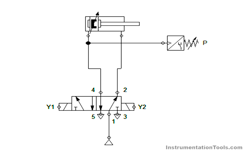
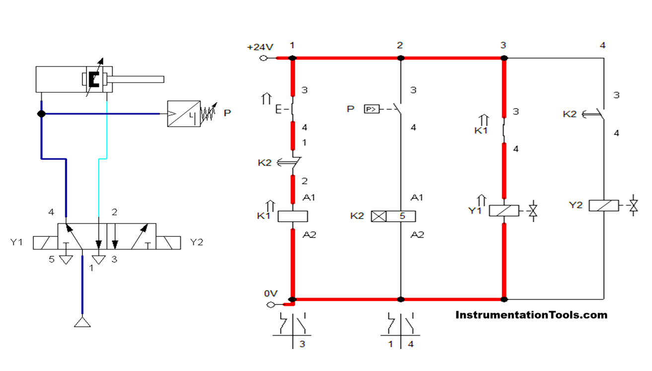
Pneumatic Circuit
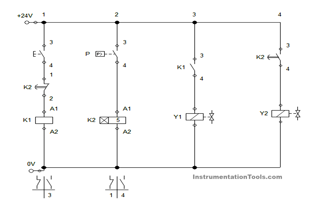
Electric Circuit
Circuit Principle
- In a pneumatic circuit, an operating pressure of 6 bar is given to the system through the compressor
- The output supply from the compressor is given to the 5/2 Direction control valve, which is connected to the double-acting cylinder. During that connection cylinder was in home position. And the Pressure sensor was connected to the extend stroke connection of the cylinder.
- In an electric circuit, power supply of 24V DC is used. Thus, the whole system was operated with the 24V only.
- Once the start button is pressed, the relay K1 is activated, which activates the solenoid coil Y1. The activation of solenoid Y1 makes the cylinder to move forward.
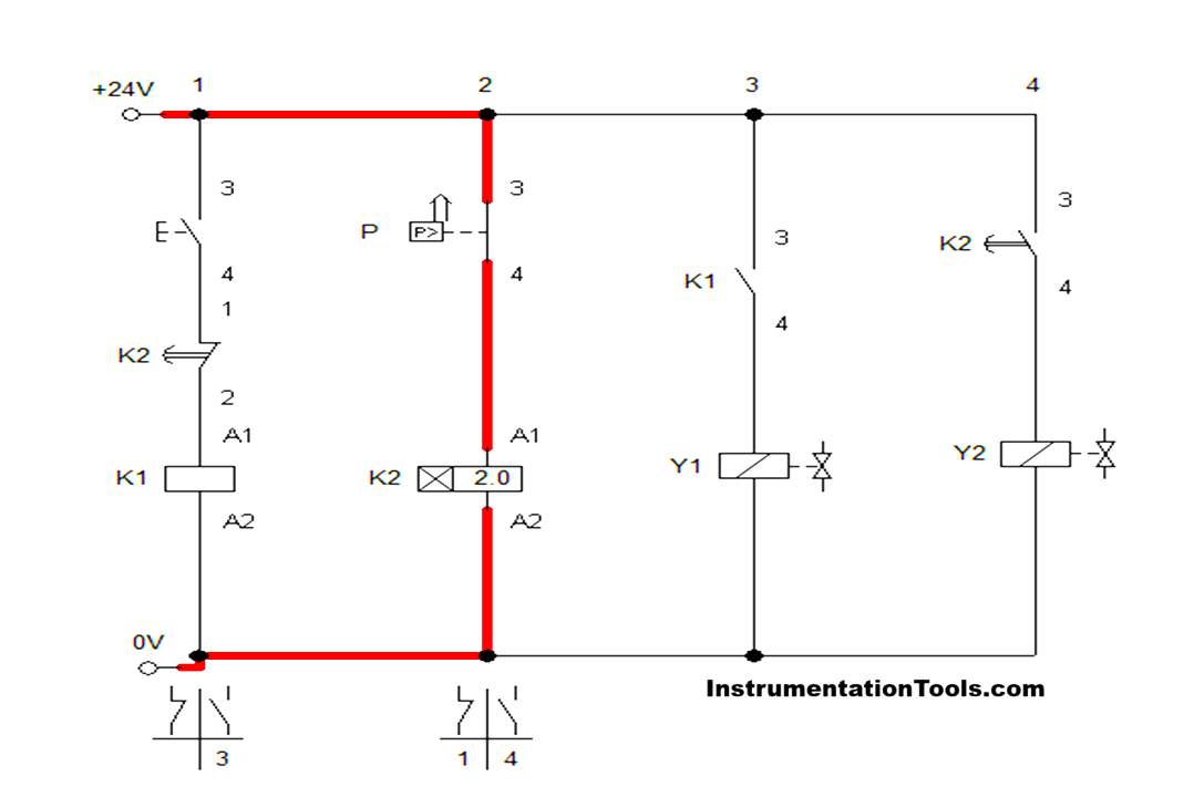
- Since the cylinder was extended forward, the pressure will be in the extended port where the pressure sensor was connected.
- In the pressure sensor, the switching pressure of 5 bar is fixed. Since the switching pressure is less than the operating pressure, the pressure sensor connection was activated in the electrical circuit.
- Activation of the pressure sensor causes the timer to activate. On-delay time of 5 second was set on the timer. Once the 5 seconds were completed on the timer, the timer connection makes the solenoid Y2 activate by breaking the connection of relay coil K1 and solenoid coil Y1.
- Activation of solenoid coil Y2 causes the cylinder to retract and makes the cycle complete. Thus, the cylinder reaches its home position, and the process will continue after pressing the start button.
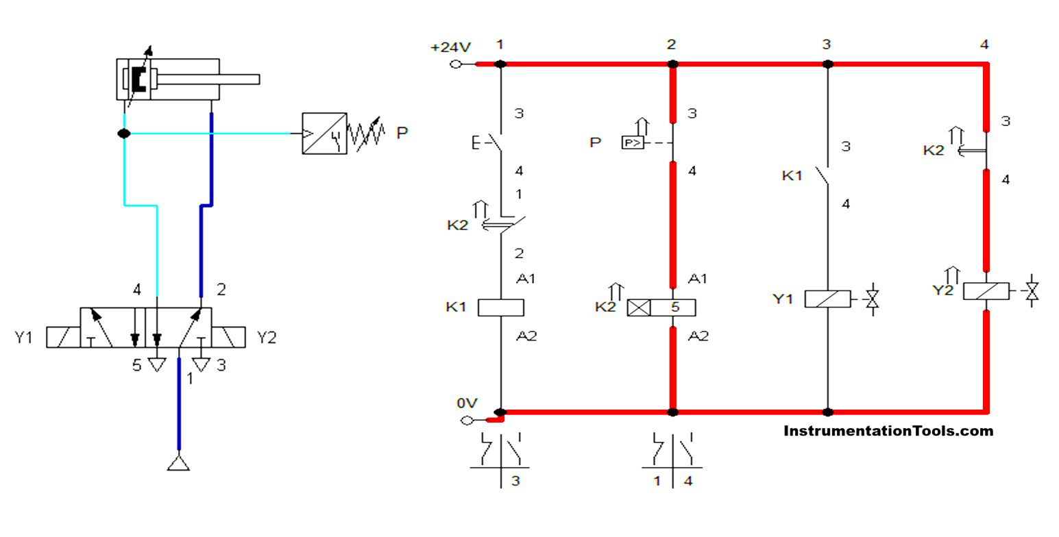
- One important factor in the circuit is, if the switching pressure in the pressure sensor is above the main air supply means it will not activate. So we need to check this while designing the circuit.
Conclusion
Thus, these types of control systems were used in industrial applications where exact timing and pressure-dependent operations were needed. For that, we are controlling the retraction motion of the cylinder with the condition of pressure and time. So, as per the requirement, the process will be done safely, reliably, and accurately in industrial automation processes.
Read Next:
- What is a Pneumatic Cylinder?
- Pneumatic Valves and Cylinders Sizing
- Sequential PLC Program Pneumatic Valve
- Control of Pneumatic Cylinder and Motor
- Master & Slave Cylinder Operation