Inst ToolsInst ToolsInst Tools
  • Courses
  • Automation
    • PLC
    • Control System
    • Safety System
    • Communication
    • Fire & Gas System
  • Instrumentation
    • Design
    • Pressure
    • Temperature
    • Flow
    • Level
    • Vibration
    • Analyzer
    • Control Valve
    • Switch
    • Calibration
    • Erection & Commissioning
  • Interview
    • Instrumentation
    • Electrical
    • Electronics
    • Practical
  • Q&A
    • Instrumentation
    • Control System
    • Electrical
    • Electronics
    • Analog Electronics
    • Digital Electronics
    • Power Electronics
    • Microprocessor
  • Request
Search
  • Books
  • Software
  • Projects
  • Process
  • Tools
  • Basics
  • Formula
  • Power Plant
  • Root Cause Analysis
  • Electrical Basics
  • Animation
  • Standards
  • 4-20 mA Course
  • Siemens PLC Course
Reading: Tank Farm Management System: CX-Programmer [OMRON]
Share
Notification Show More
Font ResizerAa
Inst ToolsInst Tools
Font ResizerAa
  • Courses
  • Design
  • PLC
  • Interview
  • Control System
Search
  • Courses
  • Automation
    • PLC
    • Control System
    • Safety System
    • Communication
    • Fire & Gas System
  • Instrumentation
    • Design
    • Pressure
    • Temperature
    • Flow
    • Level
    • Vibration
    • Analyzer
    • Control Valve
    • Switch
    • Calibration
    • Erection & Commissioning
  • Interview
    • Instrumentation
    • Electrical
    • Electronics
    • Practical
  • Q&A
    • Instrumentation
    • Control System
    • Electrical
    • Electronics
    • Analog Electronics
    • Digital Electronics
    • Power Electronics
    • Microprocessor
  • Request
Follow US
All rights reserved. Reproduction in whole or in part without written permission is prohibited.
Inst Tools > Blog > PLC Tutorials > Tank Farm Management System: CX-Programmer [OMRON]

Tank Farm Management System: CX-Programmer [OMRON]

Read the Tank Farm Management System and learn how PLC programming automates liquid level monitoring and control.

Last updated: June 29, 2025 7:28 pm
Editorial Staff
PLC Tutorials
No Comments
Share
5 Min Read
SHARE

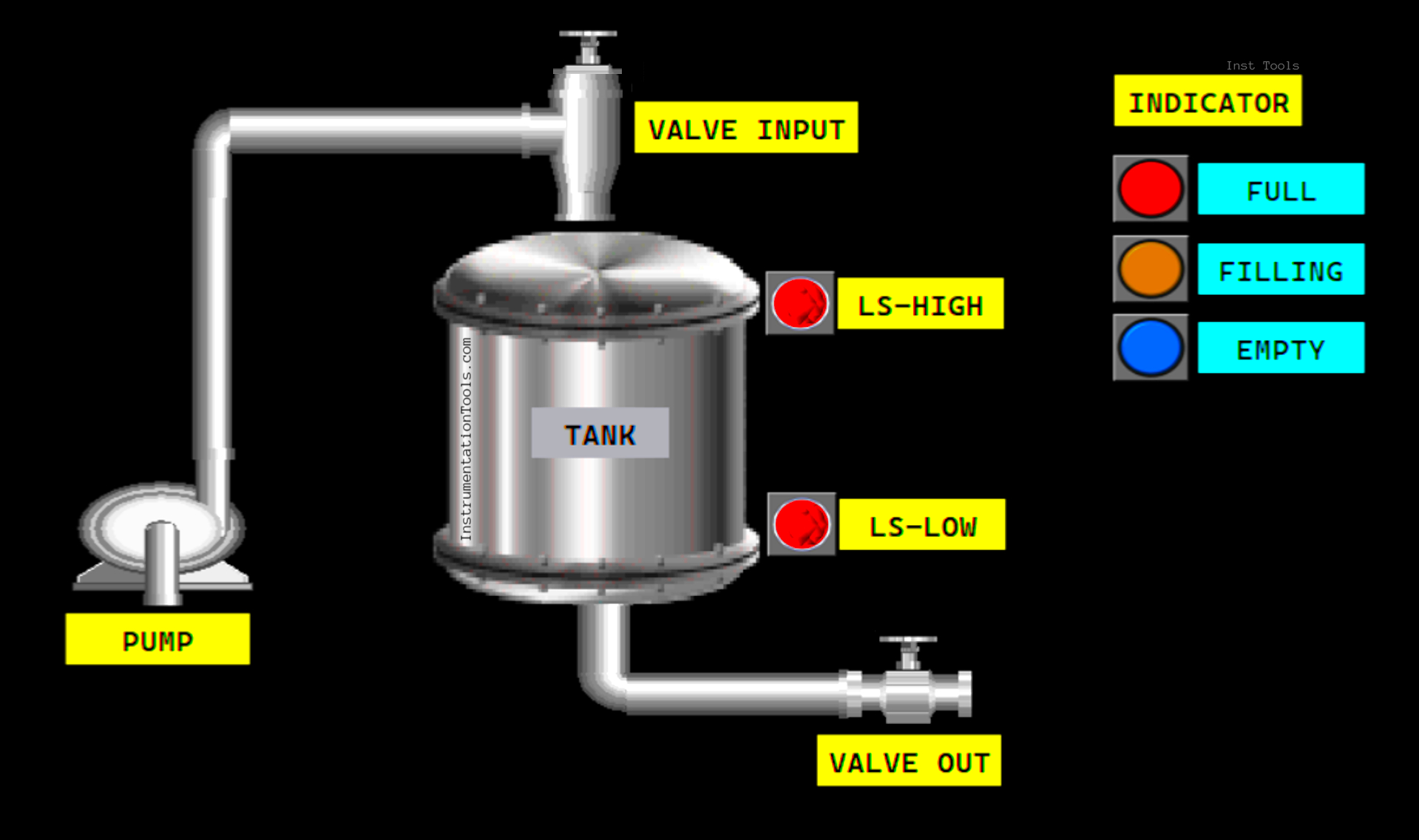
This article will discuss PLC programming to automate the process of monitoring and controlling liquid levels in a Tank Farm. This system will monitor the liquid level continuously, activate the pump to fill or empty the tank, and provide Full or Empty level indicator alarms.

Contents
Program ObjectiveCX-ProgrammerIO AddressTank Farm Management System

Program Objective

PLC Programming for Tank Farm Management

This system has:

  • Level Sensor: To measure the liquid level in the tank.
  • Pump: To fill liquid into the tank.
  • Valve: To control liquid flow.
  • Indicator: Indicator light to show system status (Full, Filling, and Empty).

When the system has been started and the liquid content in the tank is below the minimum level, the system will automatically start the filling process.

The liquid Input Valve will open, and 3 seconds later, the Pump will turn ON.

When the liquid content has reached the maximum level limit, the Input Valve will close and the Pump will turn OFF.

This system has a liquid Output Valve and can only be operated manually using a button.

CX-Programmer [OMRON PLC Program]

Tank Farm Management System CX-Programmer [OMRON]

IO Address

The program IO is addressed as follows:

CommentInput (I)Output(Q)Memory BitsTimer
START0.00   
STOP0.01   
LS_LOW0.02   
LS_HIGH0.03   
VALVE_OUT_OPEN0.04   
VALVE_OUT_CLOSE0.05   
VALVE_INPUT 100.00  
PUMP 100.01  
VALVE_OUT 100.02  
FILLING_INDICATOR 100.03  
FULL_INDICATOR 100.04  
EMPTY_INDICATOR 100.05  
TIMER1   T0000
SYSTEM_ON  W0.00 
CUTOFF_VALVE_INPUT  W0.01 


Tank Farm Management System

RUNG 0 (SYSTEM_ON)

In this Rung, when the START (0.00) button is Pressed, the memory bit SYSTEM_ON (W0.00) will be in the HIGH state. Because it uses the KEEP(011) instruction, the memory bit SYSTEM_ON (W0.00) will remain in the HIGH state even though the START (0.00) button has been Released.

The memory bit SYSTEM_ON (W0.00) will be in the LOW state if the STOP (0.01) button is Pressed.
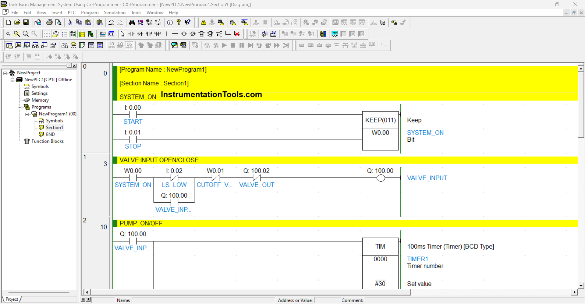
Tank Farm PLC Logic

RUNG 1 (VALVE INPUT OPEN/CLOSE)

In this Rung, if the NO contact of memory bit SYSTEM_ON (W0.00) is in the HIGH state and Sensor LS_LOW (0.02) is in the LOW state, then the output VALVE_INPUT (100.00) will be OPEN.

The VALVE_INPUT (100.00) output will be CLOSED if the NC contact of CUTOFF_VALVE_INPUT (W0.01) or VALVE_OUT (100.02) is in the HIGH state.

RUNG 2 (PUMP ON/OFF)

In this Rung, if the NO contact of VALVE_INPUT (100.00) is in the HIGH state, then Timer TIMER1 (T0000) will Start counting up to “3” seconds. When the NO contact of TIMER1 (T0000) is in the HIGH state, the PUMP (100.01) output will be ON.
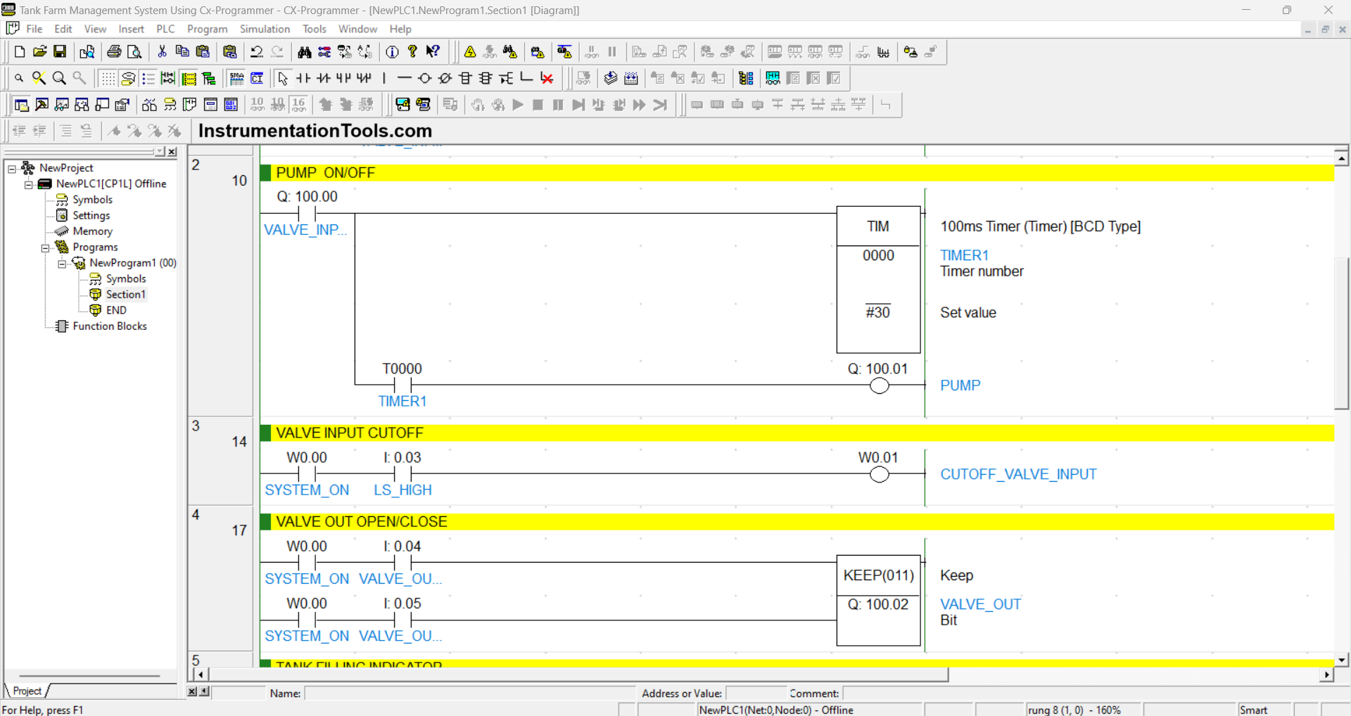
Tank management Ladder Logic

RUNG 3 (VALVE INPUT CUTOFF)

When the NO contact of memory bit SYSTEM_ON (W0.00) and Sensor LS_HIGH (0.03) are in the HIGH state, then the memory bit CUTOFF_VALVE_INPUT (W0.01) will be in the HIGH state.

RUNG 4 (VALVE OUT OPEN/CLOSE)

When the NO contact of memory bit SYSTEM_ON (W0.00) in the HIGH state and the VALVE_OUT_OPEN (0.04) button is Pressed, the VALVE_OUT (100.02) output will become OPEN. Because it uses the KEEP(011) instruction, the VALVE_OUT (100.02) output will remain in the OPEN state even though the VALVE_OUT_OPEN (0.04) button has been Released.

And when the VALVE_OUT_CLOSE (0.05) button is Pressed, the VALVE_OUT (100.02) output will become CLOSE.

RUNG 5 (TANK FILLING INDICATOR)

In this Rung, when the NO contact of PUMP (100.01) is in the HIGH state, the FILLING_INDICATOR (100.03) output will be ON.
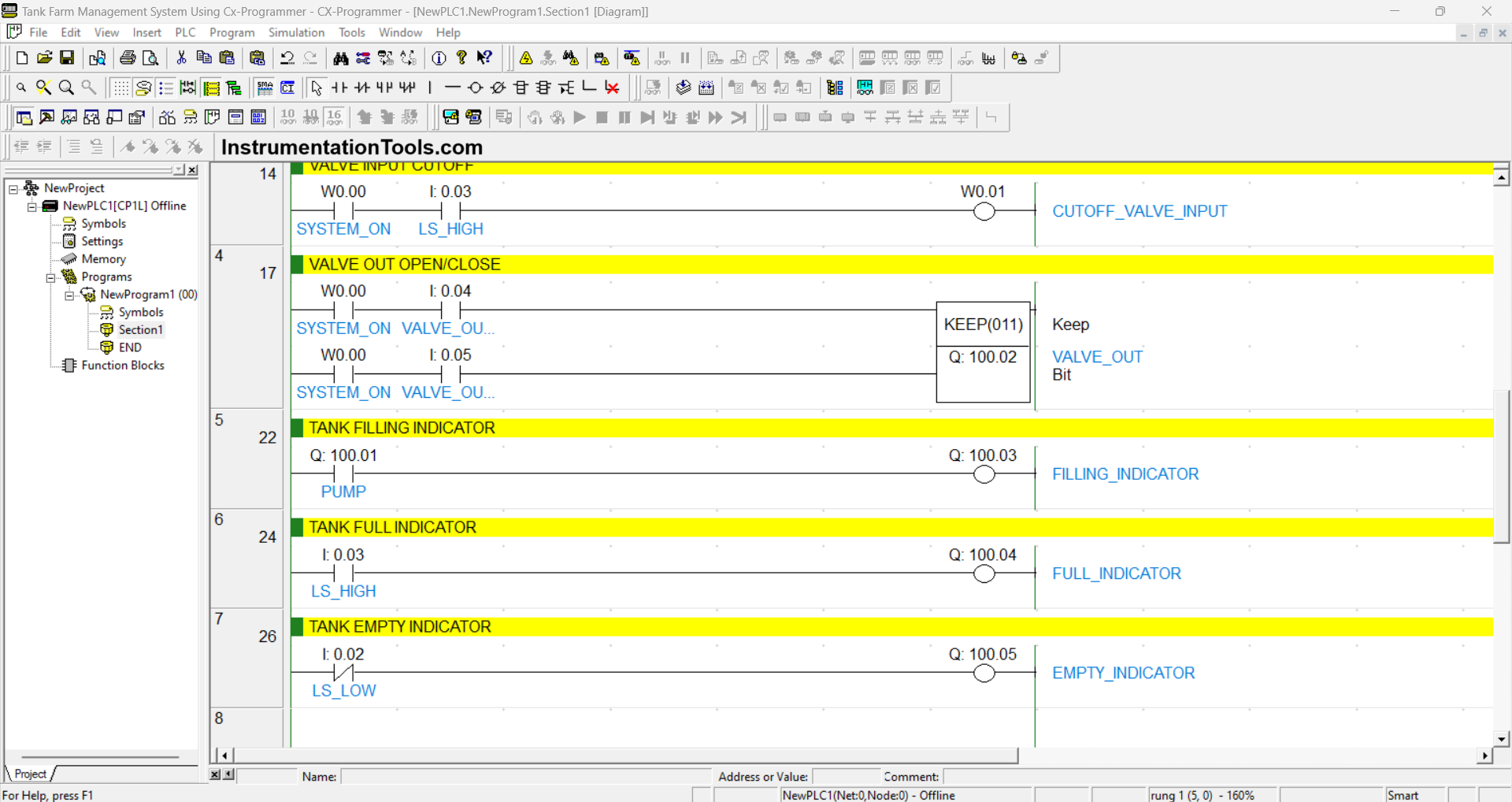
PLC Tank Terminal Monitoring and Control System

RUNG 6 (TANK FULL INDICATOR)

In this Rung, when the NO contact of Sensor LS_HIGH (0.03) is in the HIGH state, the FULL_INDICATOR (100.04) output will be ON.

RUNG 7 (TANK EMPTY INDICATOR)

In this Rung, when the NC contact of Sensor LS_LOW (0.02) is in the LOW state, the EMPTY_INDICATOR (100.05) output will be ON.

Read Next:

  • Omron PLC for Product Painting System
  • Automation in Farming & Agriculture
  • Siemens LOGO PLC Programming Course
  • Purpose of the Marshalling Cabinet
  • How to Download GX Works Software?
Don't Miss Our Updates
Be the first to get exclusive content straight to your email.
We promise not to spam you. You can unsubscribe at any time.
Invalid email address
You've successfully subscribed !

Continue Reading

Value Assignments in SCL Language – Single, Multiple, Combined
Delta HMI and VFD Control with Modbus
Connect to the Siemens S7 PLC
PLC Counter Instructions
PLC Programming for Fan Control Unit System for Industry
Basic PLC Alarm Programming Example
Share This Article
Facebook Whatsapp Whatsapp LinkedIn Copy Link
Share
Leave a Comment

Leave a Reply Cancel reply

Your email address will not be published. Required fields are marked *

Stay Connected

128.3kFollowersLike
69.1kFollowersFollow
210kSubscribersSubscribe
38kFollowersFollow

Categories

Explore More

Difference between DCS, PLC, and RTU ?
Safety Considerations in PLC System Design
What is a Line Choke or Reactor in a VFD?
SCADA System Vulnerabilities
Network Switch Requirement in SCADA and DCS Architecture
Difference Between SCADA and HMI
Drive Multiple Speeds with Different Reference using PLC
Pulse Generation using Timer in Siemens PLC

Keep Learning

PLC Timer Programming Examples on Coffee Machine

PLC Timer Practice Exercise: Coffee Machine Programming

TIA Portal MOVE Instruction

MOVE Instruction in PLC – What You Need to Know?

Conveyor Speed Logic using Structured Text in PLC

Conveyor Speed Logic using Structured Text in PLC

Siemens PCS 7

What is PCS 7?

PLC Programming Example with Pushbutton and Motor

PLC Programming Example with Pushbutton and Motor

Power Supply Sizing for Industrial Automation Systems

Power Supply Sizing for Industrial Automation Systems

How to Select the Right Encoder for Your Machine

How to Select the Right Encoder for Your Machine?

SCADA and PLC Configuration

Examples of SCADA and PLC Configuration Systems

Learn More

High-Speed Inputs in PLC

What are High-Speed Inputs in PLC?

Circular chart recorder Applications

What is Circular Chart Recorder?

Comparison of Temperature Sensors - Industrial Process Control

Comparison of Temperature Sensors – Industrial Process Control

Power Electronics Objective Questions

Quiz on Thyristor Chopper

Temperature Sensors Interview Questions

Temperature Sensors Interview Questions

magnetic flow meter parts

What is a Magnetic Flow Meter?

pressure gauge snubber

Pressure Gauge Snubbers

How to Select Right Thermocouple and Thermowell

How to Select Right Thermocouple & Thermowell ?

Menu

  • About
  • Privacy Policy
  • Copyright

Quick Links

  • Learn PLC
  • Helping Hand
  • Part Time Job

YouTube Subscribe

Follow US
All rights reserved. Reproduction in whole or in part without written permission is prohibited.
Welcome Back!

Sign in to your account

Username or Email Address
Password

Lost your password?