Inst ToolsInst ToolsInst Tools
  • Courses
  • Videos
  • Q & A
    • Interview
      • Instrumentation
      • Electronics
      • Electrical
      • Practical Questions
    • MCQ
      • Instrumentation MCQ
      • Electrical MCQ
      • Electronics MCQ
      • Control Systems MCQ
      • Analog Electronics MCQ
      • Digital Electronics MCQ
      • Power Electronics MCQ
      • Microprocessor MCQ
      • Multiple Choice Questions
  • EE
    • Electronics
      • Electronics Q & A
      • Electronic Basics
      • Electronic Devices & Circuits
      • Electronics Animation
      • Digital Electronics
    • Electrical
      • Electrical Basics
      • Electrical Q & A
      • Power Electronics
      • Electrical Machines
      • Electrical Animation
      • Power Systems
      • Switchgear & Protection
      • Transmission & Distribution
  • Measure
    • Control Valves
    • Calibration
    • Temperature
    • Pressure
    • Flow
    • Level
    • Analyzers
    • Switches
    • Vibration
    • Solenoid Valve
  • Control
    • PLC Tutorials
    • Control Systems
    • Safety Instrumented System (SIS)
    • Communication
    • Fire & Gas System
  • More
    • Design
    • Tools
    • Animation
    • Basics
    • Formulas
    • Standards
    • TextBooks
    • Common
    • Software
    • Excel Tools
    • Erection & Commissioning
    • Process Fundamentals
    • Videos
    • Books
Search
All rights reserved. Reproduction in whole or in part without written permission is prohibited.
Reading: How Process Control Loop Works
Share
Notification Show More
Font ResizerAa
Inst ToolsInst Tools
Font ResizerAa
  • Courses
  • PLC Tutorials
  • Control Systems
Search
  • Courses
  • Videos
  • Q & A
    • Interview
    • MCQ
  • EE
    • Electronics
    • Electrical
  • Measure
    • Control Valves
    • Calibration
    • Temperature
    • Pressure
    • Flow
    • Level
    • Analyzers
    • Switches
    • Vibration
    • Solenoid Valve
  • Control
    • PLC Tutorials
    • Control Systems
    • Safety Instrumented System (SIS)
    • Communication
    • Fire & Gas System
  • More
    • Design
    • Tools
    • Animation
    • Basics
    • Formulas
    • Standards
    • TextBooks
    • Common
    • Software
    • Excel Tools
    • Erection & Commissioning
    • Process Fundamentals
    • Videos
    • Books
Follow US
All rights reserved. Reproduction in whole or in part without written permission is prohibited.
Inst Tools > Blog > Control Systems > How Process Control Loop Works

How Process Control Loop Works

Last updated: July 15, 2019 4:18 pm
Editorial Staff
Control Systems
2 Comments
Share
4 Min Read
SHARE

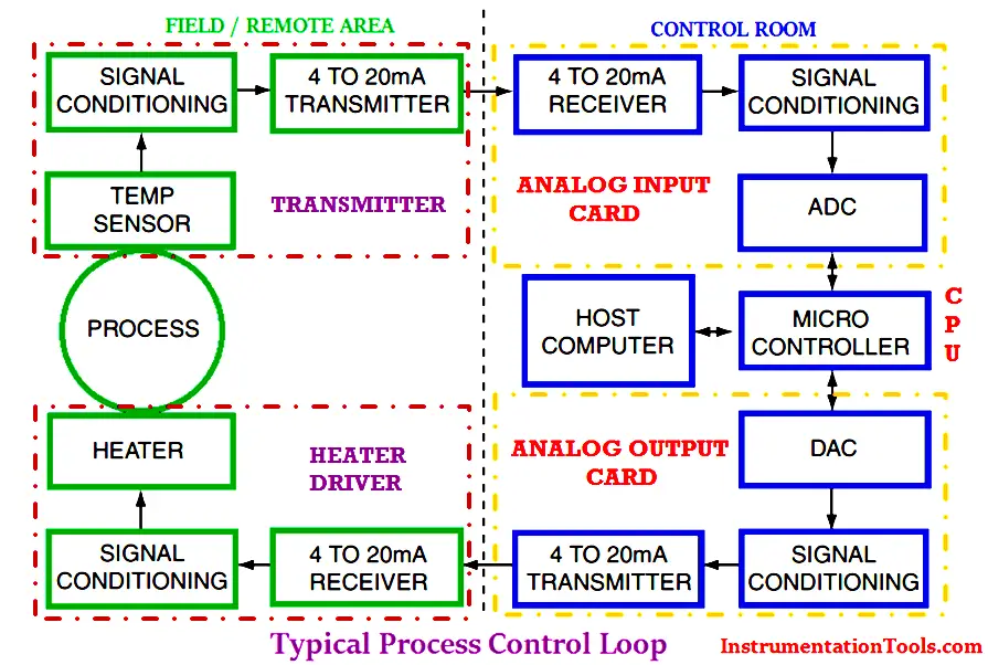
A typical process control system is shown in Figure. Assume the physical variable to be controlled is the temperature.

Basically Industrial process control loop consists of sensors, transmitters, Control systems (PLC/DCS), control valves, Electrical drives etc. These all equipment’s  installed in different areas of plant.

Typical process control loop

The Basic Plant areas classified as follows :

1.Field : Sensors, Transmitters, Control valves, on/off valves, local control panels etc.

2.Control Room : PLC, DCS, Microcontroller based controllers etc.

3.Substation : Variable Frequency Drives, Smart Feeders, Softstarters etc.

Basic Process Control Loop Example:

Now we are discussing about a basic temperature process control loop using a heater.

A Temperature Transmitters is required to measure the process variable i.e. process temperature. The transmitters have consists of sensors, signal conditioning circuit and 4-20mA converter. The transmitters basically measures the temperature and provides an output in 4-20mA current which is equivalent to measured temperature.

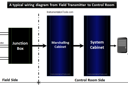
The transmitter output will goes to the PLC/DCS which is installed in control room. The transmitter wiring is terminated in Marshalling cabinet of PLC/DCS and an internal wiring is provided so that this transmitters output will  be routed from marshalling cabinet to system cabinet.

The system cabinet have Analog Input cards, Analog Output cards, Communication cards, CPU etc. As transmitters is an input to the system so it will be connected to Analog input card.

The Analog input card converts the received 4-20mA into equivalent 1-5v DC using a standard 250 ohms resistor. Then an Analog to Digital Converter (ADC) converts this 1-5V DC into equivalent Binary Codes.

The Analog input card output will be connected to the Processor (CPU). The Processor converts this binary codes into operator readable format i.e. say temperature in degrees and it will be displayed in Graphics.

Say, Now the measured temperature value found little bit high when compared to setpoint. If the loop in auto mode then PID controller will takes the necessary action automatically as per predefined program. If the loop in Manual mode then the operator has to take action manually. Note for easy discussion consider loop in auto mode.

Here in our example we have an heater which is controlling the temperature. heater have standard 4-20mA input which is used for controlling the temperature from 0 to 100% of heater range.

As assumed the measured temperature is high so PID controller decides to reduce the temperature.The Analog Output card is connected to the heater, so Processor (CPU) sends a equivalent Binary coded signal to the Analog Output card.

The Analog Output card converts the Binary coded signal using a Digital to Analog converter (DAC) which is recieved from Processor and sends an equivalent 4-20mA signal to the heater. The heater receives the 4-20mA from the PLC then takes the necessary action and finally controls the temperature to the desired value.

The Human Machine Interface (HMI) nothing but a computer used for displaying the graphics to the operator. The graphics receives all the signals from the Processor and displays to the operator.

Notice that the interface between the control room and the substation, remote process area or field is via the industry standard 4–20mA loop.
Don't Miss Our Updates
Be the first to get exclusive content straight to your email.
We promise not to spam you. You can unsubscribe at any time.
Invalid email address
You've successfully subscribed !

Recommended Articles

Power Supply Sizing for Industrial Automation Systems
What is Alarm Prioritization? – Types of Alarms
Inspection and Testing of Fiber Optic Cable
Workstation Healthiness Checks
Control System Architecture
Electrical and Instrumentation – Automation Pre-engineering Documents
Share This Article
Facebook Whatsapp Whatsapp LinkedIn Copy Link
Share
2 Comments
  • Roc Shieh says:
    August 15, 2016 at 5:07 am

    A good process control loop diagram. I like.

    Reply
  • Babu KR says:
    December 17, 2016 at 5:29 am

    Excellent explanations. Understandable, simple & clear.

    Reply

Leave a Reply Cancel reply

Your email address will not be published. Required fields are marked *

Stay Connected

128.3kFollowersLike
69.1kFollowersFollow
208kSubscribersSubscribe
38kFollowersFollow

Categories

Recent Comments

  • William Snyder on Top Non-PLC Certification Courses for Automation Professionals
  • Kamli on Top Free PLC Software
  • Guifty Shimica on Top Non-PLC Certification Courses for Automation Professionals
  • Guifty Shimica on Top Non-PLC Certification Courses for Automation Professionals

Related Articles

Commissioning Checklist for Industrial Automation System

Commissioning Checklists for Industrial Automation Systems

Instrumentation Engineer Interview Questions

Interview Questions on PID Controllers

PV Tracking in PID Controllers

What is PV Tracking ?

Smart HART Transmitter

Analysis of HART communicator and Smart HART Transmitter

Industrial Automation Architecture reference model

Industrial Automation System Architecture Reference Model

Turbine-Compressor System Architecture

Turbine-Compressor System Architecture

SCADA RTU TELEMETRY

SCADA & Telemetry Systems

Project Planning and Implementation of PLC or DCS Control System

Project Planning and Implementation of PLC or DCS Control System

More Articles

Process Variable Damping Graph

Process Variable Damping of Transmitter

Generator Action in a Motor

Generator Action in a Motor

Why Grounding

Generating Station Grounding Principles

Electrical and Instrument Engineers Job Profile

Instrumentation and Electrical Teams Interactions (Detail Design Engineering)

Problem with Pirani Gauge

Problem with Pirani Gauge

Pressure Gauge Calibration Procedure

simple latching motor control circuit

Motor Control Circuit Wiring

Magnetostrictive Level Transmitter Working Principle

Magnetostrictive Level Transmitter Working Principle

Follow US
All rights reserved. Reproduction in whole or in part without written permission is prohibited.
Welcome Back!

Sign in to your account

Username or Email Address
Password

Lost your password?