Inst ToolsInst ToolsInst Tools
  • Courses
  • Automation
    • PLC
    • Control System
    • Safety System
    • Communication
    • Fire & Gas System
  • Instrumentation
    • Design
    • Pressure
    • Temperature
    • Flow
    • Level
    • Vibration
    • Analyzer
    • Control Valve
    • Switch
    • Calibration
    • Erection & Commissioning
  • Interview
    • Instrumentation
    • Electrical
    • Electronics
    • Practical
  • Q&A
    • Instrumentation
    • Control System
    • Electrical
    • Electronics
    • Analog Electronics
    • Digital Electronics
    • Power Electronics
    • Microprocessor
Search
  • Books
  • Software
  • Projects
  • Process
  • Tools
  • Basics
  • Formula
  • Power Plant
  • Root Cause Analysis
  • Electrical Basics
  • Animation
  • Standards
  • 4-20 mA Course
  • Siemens PLC Course
Reading: Acceptable Earth Resistance Values
Share
Notification Show More
Font ResizerAa
Inst ToolsInst Tools
Font ResizerAa
  • Courses
  • Design
  • PLC
  • Interview
  • Control System
Search
  • Courses
  • Automation
    • PLC
    • Control System
    • Safety System
    • Communication
    • Fire & Gas System
  • Instrumentation
    • Design
    • Pressure
    • Temperature
    • Flow
    • Level
    • Vibration
    • Analyzer
    • Control Valve
    • Switch
    • Calibration
    • Erection & Commissioning
  • Interview
    • Instrumentation
    • Electrical
    • Electronics
    • Practical
  • Q&A
    • Instrumentation
    • Control System
    • Electrical
    • Electronics
    • Analog Electronics
    • Digital Electronics
    • Power Electronics
    • Microprocessor
Follow US
All rights reserved. Reproduction in whole or in part without written permission is prohibited.
Inst Tools > Blog > Electrical Basics > Acceptable Earth Resistance Values

Acceptable Earth Resistance Values

Every country has defined some set of standard acceptable earth resistance values for every electrical device and equipment.

Last updated: September 13, 2024 12:51 pm
Viral Nagda
Electrical Basics
No Comments
Share
5 Min Read
SHARE

In any instrument or electrical device, one of the most important parameters to consider is earthing. We know that any such device cannot function properly without proper earthing, as it will damage them from leakage currents or EMI (electromagnetic interference) currents after prolonged use.

Contents
What is earthing? Why is earthing of electrical devices necessary?What is earth resistance?Acceptable Earth Resistance Values in India

So, when you are designing earthing pits for them, you need to know their acceptable resistance values in India before giving them for use. In this post, we will see the acceptable earth resistance values in India.

What is earthing? Why is earthing of electrical devices necessary?

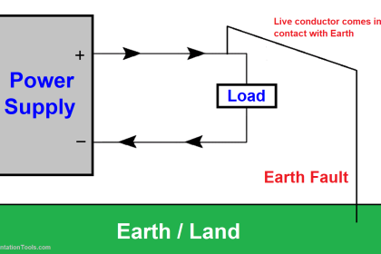
Many times, there can be a fault in an electrical device, where the design of conductive or insulation path may not be proper. In such a case, current will leak through the body and when someone accidentally touches it or if it comes in contact with some other live circuit, then it will create a short circuit or cause damage to human life. So, there needs a path to divert this leakage current or transient voltage into a safe location. This is done through earthing.

Earthing provides a path for the faulty current to flow into the ground through a protective conductor. This will reduce all the possibilities for getting any short circuit or damage nearby. It thus allows the flow of excess electricity from the device to the ground.

Acceptable Earth Resistance Values

What is earth resistance?

Practically, it is impossible for all of the leakage current to flow into the ground. It is just theoretical, not practical. Theoretically, it means zero resistance to the current, which allows all of the current to flow into the ground. But, some resistance is offered which results only a certain percentage of current to flow. This resistance applied for the earth electrode to the flow of electricity is earth resistance. The earthing resistance value is based upon the soil resistivity, construction design, and climate-related conditions.

When the leakage current flows through the electrode, that electrode will transfer the current to many areas in the soil surrounding it.  The soil property will not be the same in each and every inch surrounding the electrode. Some will be soft or some will be hard. So, as the soil properly is not the same in all the areas, some amount of leakage current will not be flown as a proper path will not be given. This makes it important to measure earth resistance around the electrode. The lesser the value, the very good chances are for passing leakage current to the ground as much as possible.

The four most important factors affecting earth resistance are –

  • soil composition,
  • moisture content in the soil,
  • temperature of soil and
  • depth of earth electrode into the ground.

Acceptable Earth Resistance Values in India

Every country has defined some set of standard acceptable values of earthing, depending upon their general climate, soil quality and frequency of applied voltage (for example 50 hZ in India). Like that, we will see what are the standard values in India:

  1. Power stations – 0.5 ohms
  2. EHT stations – 1.0 ohms
  3. 33KV substations – 2 ohms
  4. DTR structures – 5 ohms
  5. Tower foot resistance – 10 ohms

If the value around that earth pit electrode is below or equal to this value, then it means the resistance for the required device is low and will allow a good amount of leakage current to pass to the ground.

Ground Rod

Some common ways to lessen earth resistance are – adding salt around the electrode, using longer electrodes for a deeper reach in the earth, adding special coatings to the electrode layer for corrosion protection, and adding moisture-retaining substances around the electrode to keep the moisture content in control.

In this way, we saw the acceptable earth resistance values in India.

Read Next:

  • Instrumentation Earthing
  • Instrumentation and Electrical Teams
  • PLC Wiring Questions for Technicians
  • PLC Panel and MCC Panel Interface Signals
  • Earthing Practices Used for PLC Control Panel
Don't Miss Our Updates
Be the first to get exclusive content straight to your email.
We promise not to spam you. You can unsubscribe at any time.
Invalid email address
You've successfully subscribed !

Continue Reading

How to Connect a 3 Phase Motor in Star and Delta Connections?
100 Electronics and Electrical Projects for Engineering Students
UPS Working Principle and Types – Offline and Online UPS Systems
Electrical Switches Principle & Types
What is an HRC Fuse? – Material, Types, Advantages
What is a Lightning Arrester? How does it work?
Share This Article
Facebook Whatsapp Whatsapp LinkedIn Copy Link
Share
Leave a Comment

Leave a Reply Cancel reply

Your email address will not be published. Required fields are marked *

Stay Connected

128.3kFollowersLike
69.1kFollowersFollow
210kSubscribersSubscribe
38kFollowersFollow

Categories

Explore More

How to Read the Nameplate of a Motor?
Difference Between Power Cable and Instrument Cable
Difference Between MPCB and MCCB
Things to Know When Measuring Voltage
Stepper Motor Working Principle
Download Electrical Enclosure Book
What is Electrical Conduit? Types, Advantages, Disadvantages
What is Electrical Busbar? Types, Advantages, Disadvantages

Keep Learning

Electrical Terminal Blocks

How to Protect Electrical Terminal Blocks From Tampering?

What is Electrical Interlocking?

Electrical Contactor Interlocking Circuit Explained

Induction Motor Operation

Induction Motor Over and Under Voltage Problems

Time Delay Fuse

What is a Time Delay Fuse? – Principles and Advantages

Electrical Cabinet Air Conditioner

Electrical Cabinet Air Conditioner – Enclosure Cooling, Maintenance

Difference Between Metering CT and Protection CT

Difference Between Metering CT and Protection CT

Floating Neutral - Electrical Engineering Basics

What is Floating Neutral? – Electrical Engineering Basics

Intelligent MCC

What is Smart or Intelligent MCC?

Learn More

Single-acting Pneumatic Cylinder operation with Limit Switch

Single-acting Pneumatic Cylinder Operation with Limit Switch

How to Solve Cable Tray Sagging

How to Solve Cable Tray Sagging ?

Electric Bell Working animation

Electric Bell Working animation

Sample Schematic Template for Systems Architecture Diagram

Design Document for Project Systems Architecture

Global Data Blocks in PLC

What is a Data Block? Global Data Blocks in PLC

Oil in Water Analyzer Principle

Oil in Water Analyzer Working Principle

Quick Exhaust Valve (QEV)

Quick Exhaust and Air Operated Valves in Instrumentation Circuit

Insulators, Conductors and Semiconductors

Menu

  • About
  • Privacy Policy
  • Copyright

Quick Links

  • Learn PLC
  • Helping Hand
  • Part Time Job

YouTube Subscribe

Follow US
All rights reserved. Reproduction in whole or in part without written permission is prohibited.
Welcome Back!

Sign in to your account

Username or Email Address
Password

Lost your password?