Shaping is commonly used to produce flat surfaces it may be horizontal, vertical, or inclined by machining with the reciprocating tool. It can as well machine varieties of curved, odd, and irregular surfaces composed of straight-line elements. This machine is also capable of generating contour surfaces.
A Shaper machine is a reciprocating type of machine tool where in the rotary motion of the motor is converted into the reciprocating movement of the ram by the mechanism housed within the column of the machine.
In a standard shaping machine tool cuts metal in its forward stroke only and the return stroke goes idle as no metal is cut during the return stroke.
This feature is achieved in a shaper with the help of two mechanisms.
- Crank and Slotted Mechanism
- Hydraulic Shaper Mechanism
Hydraulic Shaper Mechanism
In the hydraulic shaper mechanism, the ram is connected to the left-hand end of the piston rod which moves in a hydraulic cylinder placed under the ram.
In this, hydraulic oil is discharged with the help of a pump under higher pressure which passes through the directional control valve and then enters the hydraulic cylinder from the right-hand side, and exerts pressure on the piston.
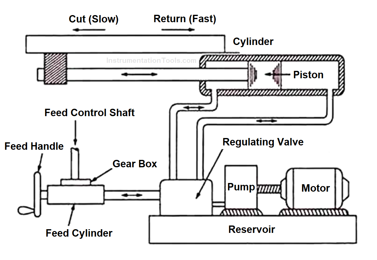
Hydraulic Shaping Machine Diagram
This makes the ram perform the forward stroke while any oil present on the left-hand side of the cylinder is discharged to the reservoir. At the completion of the forward stroke, the shaper dog hits against the limit switches. Because of this, oil under high pressure is now pumped on the left side of the piston causing the ram to perform return stroke.
Some of the advantages of using a hydraulic shaper mechanism are constant cutting and return speeds throughout the stroke, the length of the stroke and its position relative to work may be changed quickly, and ram movement can be reversed instantly.
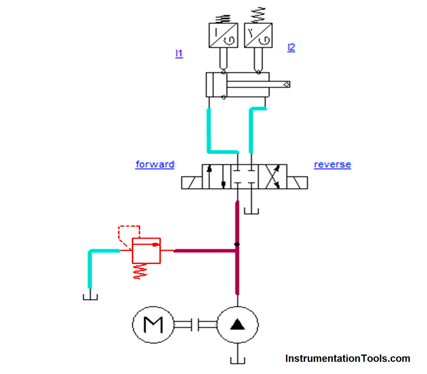
Hydraulic Shaper Machine – Hydraulic Circuit
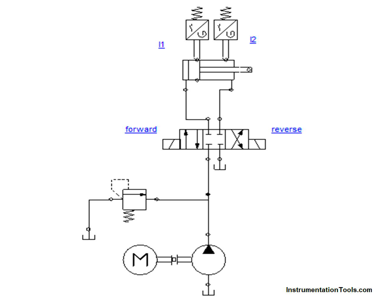
Components used in Hydraulic Circuit
- Unidirectional Pump and Prime Mover
- 4/3 Directional Control Valve
- Pressure Relief Valve
- Limit Switches
- Double Acting Cylinder
- Reservoir (or) Tank
Unidirectional Pump and Prime Mover
The prime mover is usually an electric motor which was directly coupled to the pump.
The pump is the heart of the system which converts the mechanical energy into hydraulic energy that produces the high pressure which forces the oil into the system
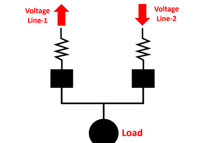
4/3 Directional Control Valve
The 4/3 directional control valve used in the system has two output ports, one pressure port, and one exhaust port.
When the spool is in the left position, the pressure port is connected to one of the output ports which makes the cylinder move forward and if the spool is in the right position, the pressure port will be shifted to another port which makes the cylinder move backward. At the same time, from another port, the fluid is returned to the reservoir.
Pressure Relief Valve
In a fluid power system, the components are designed for a certain pressure. If the pressure exceeds the normal pressure it may burst.
In order to avoid the accident, the pressure should not rise above the normal working pressure. The device used to maintain the pressure at a normal level is the pressure relief valve.
Limit Switches
Limit switches are mechanically actuated switch which is used to sense the end position of the cylinder. It acts as input for doing the further operation in the system.
Double Acting Cylinder
The cylinder is a component that consists of a piston and a piston rod. It looks like a circular tube sealed at both ends.
In a double-acting cylinder, the hydraulic fluid is applied on one side which makes the piston extend forward and if the fluid is applied on another side then the piston will retract backward and the fluids on the cylinder will move to the reservoir
Reservoir (or) Tank
A reservoir or tank is the place where the hydraulic fluids are stored. The suction of the pump is connected to the reservoir from which the fluid is forced into various hydraulic elements by the action of the pump.
Hydraulic Shaper Machine – Electrical Circuit
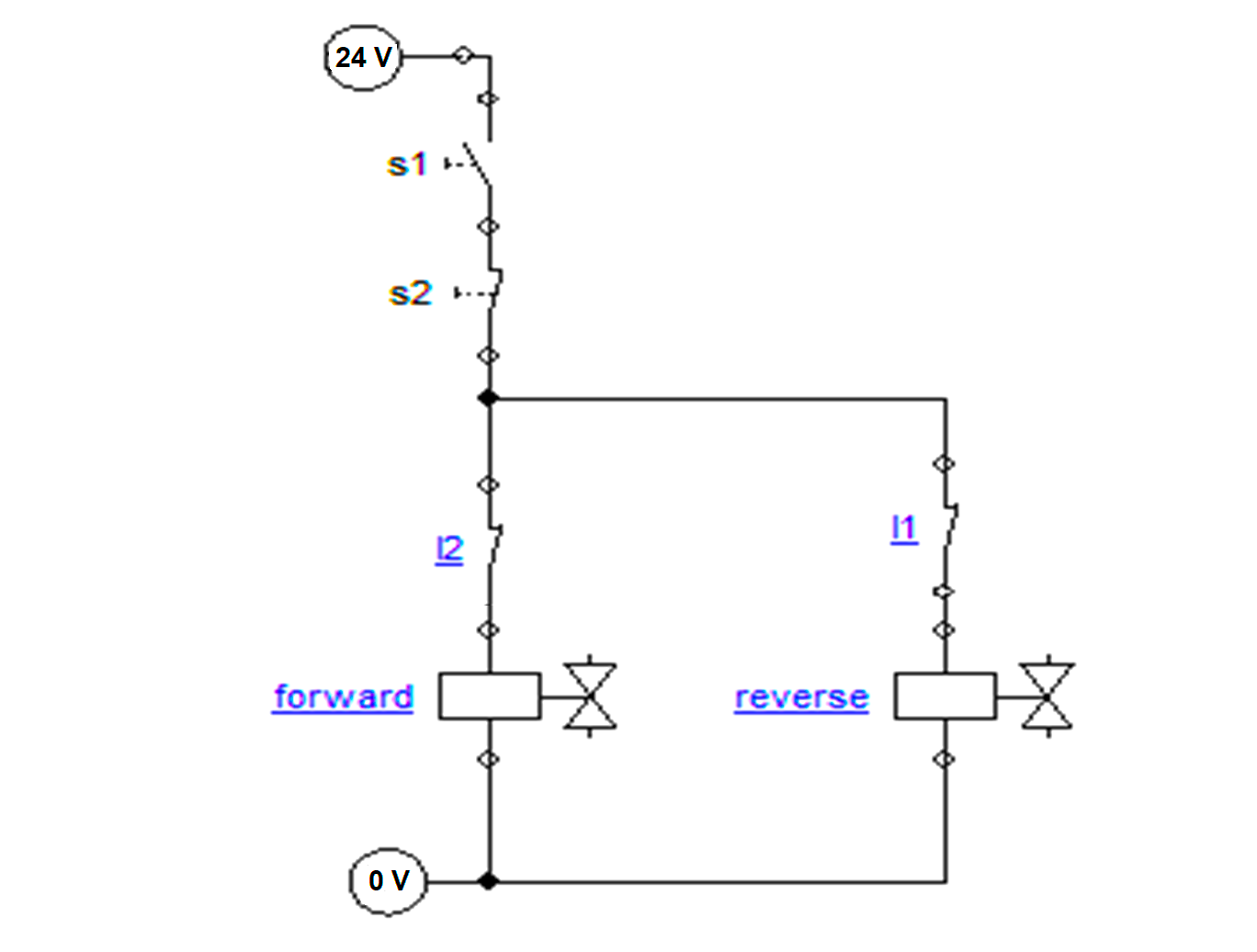
Components used in Electrical Circuit
- Start & Stop Switches
- Valve Solenoid
Start & Stop Switches
The system starts with a Start switch -S1 (NO Switch) and the system stops with stop switch – S2 (NC Switch).
If the stop is in energized (On) condition the system will not be operated even if we turn or energize the start switch. The stop switch is used as an emergency switch.
Valve Solenoid
Solenoid valves work with the electromagnetic principle. In our circuit, we use a 24V Power supply. Once this valve solenoid is activated it gives a signal to a directional control valve that makes the spool movement which moves the cylinder forward or reverse.
In this, we used two valve solenoids for forward and reverse movement of the cylinder.
Hydraulic Shaper Machine Working Principle
A shaping machine is used to produce a flat surface on the component. So it requires a horizontal movement of the tool. The horizontal movement is done by the hydraulic ram.
When 4/3 is in the middle position, the pump supply directly goes to the reservoir resulting in no action in the cylinder.
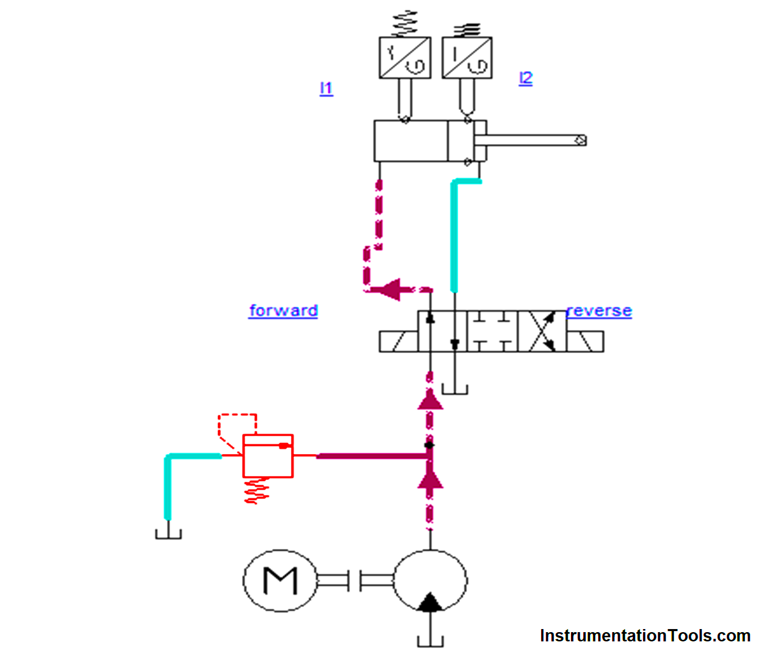
After pressing the start switch, the DCV will shift towards the right, the pump supply enters the hydraulic circuit cylinder at the right port which causes the cylinder to move forward.
Since the ram and cutting assembly are connected to the piston rod, the tool moves in the forward direction and removes the material. At the same time, oil on the left side directly flows to the reservoir.
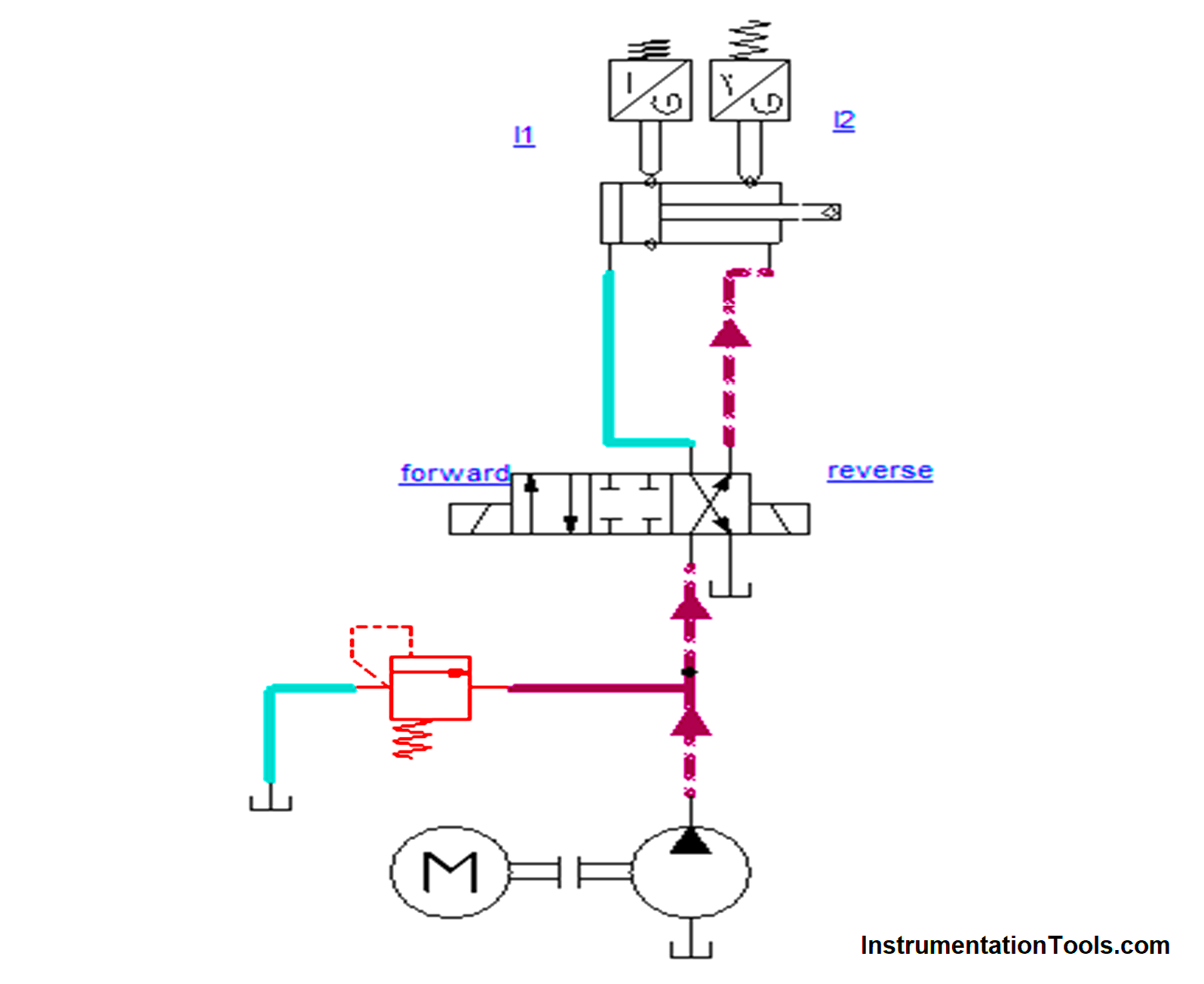
Once the cylinder extends to its end position and its position is sensed by limit switch 2 which makes DCV shift towards the left, the pump supply enters the cylinder at the left port which causes the cylinder to move backward.
At the time, oil in the right-side id flows to the reservoir, As per the construction of the shaper machine on its reverse movement it will not remove the material.
Again, it will touch the limit switch 1 which makes the cylinder move forward and makes the continuous process. Once we press the stop switch the process will stop. If the pressure exceeds the normal level, then pressure relief maintains the balance level in the system by its action.
By this action, the hydraulic shaping machine ram is actuating forward & backward, and with the control of handle movements the left and right movement is controlled.