Inst ToolsInst ToolsInst Tools
  • Courses
  • Automation
    • PLC
    • Control System
    • Safety System
    • Communication
    • Fire & Gas System
  • Instrumentation
    • Design
    • Pressure
    • Temperature
    • Flow
    • Level
    • Vibration
    • Analyzer
    • Control Valve
    • Switch
    • Calibration
    • Erection & Commissioning
  • Interview
    • Instrumentation
    • Electrical
    • Electronics
    • Practical
  • Q&A
    • Instrumentation
    • Control System
    • Electrical
    • Electronics
    • Analog Electronics
    • Digital Electronics
    • Power Electronics
    • Microprocessor
  • Request
Search
  • Books
  • Software
  • Projects
  • Process
  • Tools
  • Basics
  • Formula
  • Power Plant
  • Root Cause Analysis
  • Electrical Basics
  • Animation
  • Standards
  • 4-20 mA Course
  • Siemens PLC Course
Reading: Testing of Thermal Protection Relay for Motors
Share
Font ResizerAa
Inst ToolsInst Tools
Font ResizerAa
  • Courses
  • Design
  • PLC
  • Interview
  • Control System
Search
  • Courses
  • Automation
    • PLC
    • Control System
    • Safety System
    • Communication
    • Fire & Gas System
  • Instrumentation
    • Design
    • Pressure
    • Temperature
    • Flow
    • Level
    • Vibration
    • Analyzer
    • Control Valve
    • Switch
    • Calibration
    • Erection & Commissioning
  • Interview
    • Instrumentation
    • Electrical
    • Electronics
    • Practical
  • Q&A
    • Instrumentation
    • Control System
    • Electrical
    • Electronics
    • Analog Electronics
    • Digital Electronics
    • Power Electronics
    • Microprocessor
  • Request
Follow US
All rights reserved. Reproduction in whole or in part without written permission is prohibited.
Inst Tools > Blog > Electrical Basics > Testing of Thermal Protection Relay for Motors

Testing of Thermal Protection Relay for Motors

In this article, you will learn the testing procedure of thermal protection relay for electrical motors.

Last updated: March 4, 2022 9:15 am
Editorial Staff
Electrical Basics
2 Comments
Share
3 Min Read
SHARE

The first thing to do after purchasing a new device is to test it and install it in the field if it is OK.

The main purpose of this post is to discuss the testing procedure of my today’s device Thermal Protection Relay.

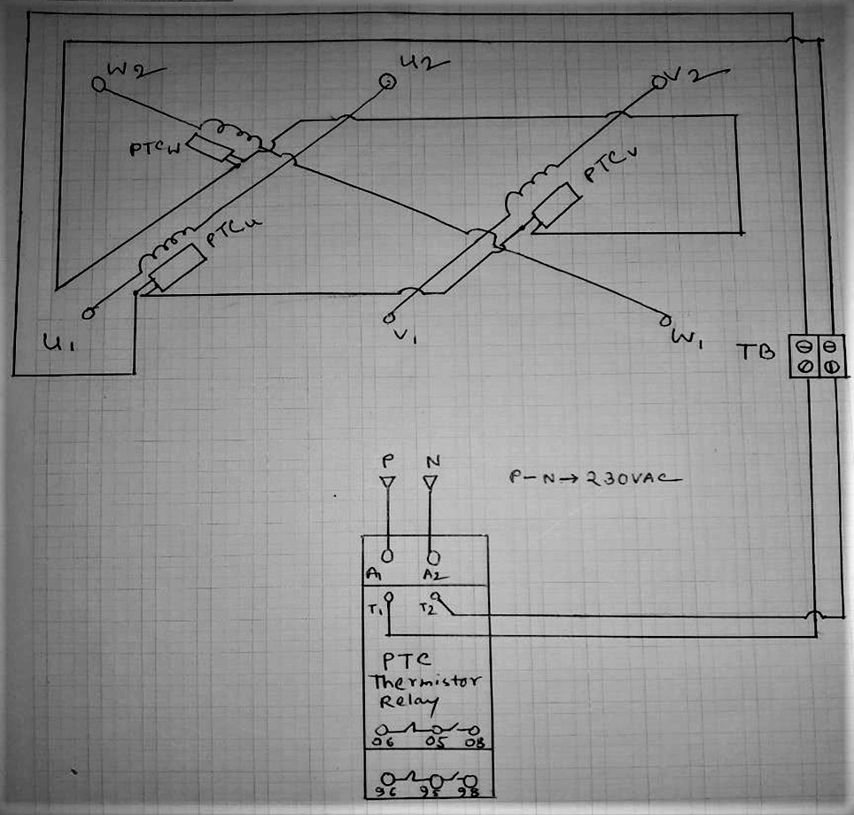
The thermistor-protected three-phase induction motor has a total of three PTC thermistors in each of the windings which are connected to the terminal block by two cables connected to each other in series (follow Figure 1).

Thermal Protection Relay for Motors
Thermal Protection Relay for Motors
Figure 1

For the purpose of testing, I connected two cables from the terminal block of the motor to the T1, T2 terminal of the reel as per Figure 1. Then I did the wiring for the coil supply voltage at relay A1, A2 terminal, I had this relay 230VAC coil.

Before turning on the coil supply, I checked the resistance at the T1, T2 terminal with a multimeter to see if the thermistor connection was working properly, I got a reading of 285 ohms (this is the value) Now come to auxiliary contact.

These types of protection devices usually have the Fail-Safe feature, meaning that the device will automatically change its status from normal to auxiliary if the device is faulty or dead.
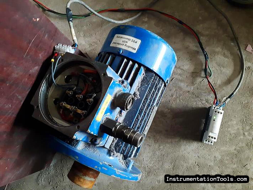
Commissioning of Thermal Protection Relay for Motors
Figure 2

So before turning on the coil supply I found the NO contacts of the relay in closed condition and the NC contacts in open condition – meaning if there is a thermal fault in the motor then the auxiliary contact will be in the same condition as in the device dead. That means the device is OK.

This time after turning ON the coil supply, the green indicator flashed and NO contact was opened and NC contact was found closed, which means that it is OK in normal operation. (check the relay status indicators on the above image)
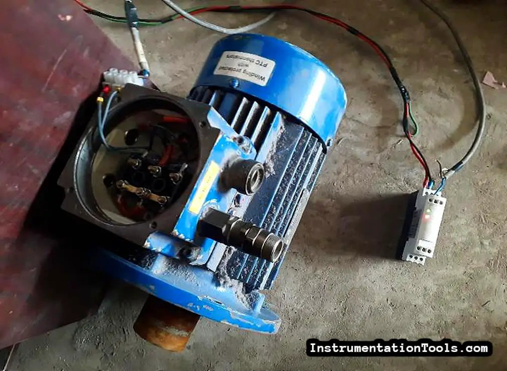
Thermal Protection Relay Testing and Commissioning
Figure 2: Relay ON

Now the fault is lit by manually creating a fault by disconnecting the cable from the T1 terminal and the NO and NC contacts are closed and open, respectively. (check the relay status indicators on the above image)

Some of these relays are also available with a test button that can be pressed to check the functionality of a regular device.

… thank you all …

Author:

Amit Banerjee

Electrical Engineering professional with 10+ years of experience in industrial automation and maintenance activities. Worked at different manufacturing facilities and process plants along with experience of erection, commissioning of LPG filling process plant.

Don't Miss Our Updates
Be the first to get exclusive content straight to your email.
We promise not to spam you. You can unsubscribe at any time.
Invalid email address
You've successfully subscribed !

Continue Reading

What is a Lightning Arrester? How does it work?
Preventive Maintenance of Variable Frequency Drive (VFD)
Why is HV Testing important in Electrical Panels?
Basic Electrical Engineering Questions & Answers
What is a Damper? Types of Dampers in HVAC
Technical Specification for Uninterrupted Power Supply (UPS) System
Share This Article
Facebook Whatsapp Whatsapp LinkedIn Copy Link
Share
2 Comments
  • Nguyễn Đức Thanh says:
    March 4, 2022 at 12:31 pm

    Sorry. As I see your explanation about the relay and from what I know, if we give power to the coil of relay, the status of NO contact will be closed and the status of NC contact will be opened. I think you made some wrong explain about the operation principles of relay

    Reply
    • Engr. Amit Banerjee says:
      March 6, 2022 at 3:02 pm

      This will happen (like you said) when thermal breakdown of windings will happen inside motor or the thermistor wires are broken (both along with coil supply power on) or device power is dead…
      But in healthy condition along with coil supply power on, contacts won’t change their states.
      Thank you…

      Reply

Leave a Reply Cancel reply

Your email address will not be published. Required fields are marked *

Stay Connected

128.3kFollowersLike
69.1kFollowersFollow
210kSubscribersSubscribe
38kFollowersFollow

Categories

Explore More

What is Electrical Slip Ring? Principle, Types, Advantages, Applications
How to Operate a Group of Induction Motors using PLC Logic?
What is a Bus Coupler in Electrical Panel?
What is an ELV System? – Extra Low Voltage
Difference Between AIS and GIS Panels
Electrical Feeder Automation in Smart Grid
Safety Tips When Working With Electricity
Variable Frequency Drive (VFD) Working Principle

Keep Learning

Corona Discharge

Corona Discharge in Power Transmission Lines

Top Electrical Engineering Questions & Answers

Top Electrical Engineering Questions & Answers

Electrical Engineering Documents

Electrical Engineering Documents – Engineers Questions

Difference Between Emergency STOP and Emergency Power OFF

Difference Between Emergency STOP and Emergency Power OFF

DOL Starter Testing

DOL Starter – Working, Circuit, Advantages, Disadvantages, Applications

Electrical bonding jumpers

Proper Sizing of Conductors

Characteristics of Protective Relay

What is a Protective Relay? Principle, Advantages, Applications

corroded tank

Cathodic Protection – Sacrificial Anodic and Impressed Current

Learn More

basic-electronics-questions-answers

Basic Electronics Questions & Answers

Bucket Steam Trap

Bucket Steam Trap

SCADA Run

PLC Based Industrial Conveyor Ladder Logic

diode-clamper-circuit

Full Wave Voltage Doubler using Diodes

Robotic Process Automation

What is Robotic Process Automation? Advantages, Applications

Emerson ASCO Solenoid valve references

SIS Solenoid Valves – Safety PLC

Center Tap Full-Wave Rectifier

Full-Wave Rectifier Circuit

Span of Pressure Gauge

How to Decrease Span of Pressure Gauge?

Menu

  • About
  • Privacy Policy
  • Copyright

Quick Links

  • Learn PLC
  • Helping Hand
  • Part Time Job

YouTube Subscribe

Follow US
All rights reserved. Reproduction in whole or in part without written permission is prohibited.
Welcome Back!

Sign in to your account

Username or Email Address
Password

Lost your password?