One of the many parameters that must be accurately measured for product quality control, custody transfer, process control, or liquid interface detection purposes is liquid density. Often density measurement is combined with flow measurement to determine the mass flow rate of a liquid in a pipeline. What follows is a discussion of the principle of operation of vibrating tube densitometers.
Densitometer Types
There are different types of densitometers in use today. Some of the various operational principles for these devices are: vibration, buoyancy, nuclear, and acoustic. Each operation principle has advantages and disadvantages.
The selection of the densitometer type usually depends on the application, performance requirements, and budget. We will restrict these discussions to vibrating tube densitometers.
Operating Principle
The simplest vibrating system consists of a spring and mass that are mechanically connected. If the mass is displaced and released, the system will vibrate at a known frequency defined by the equation,
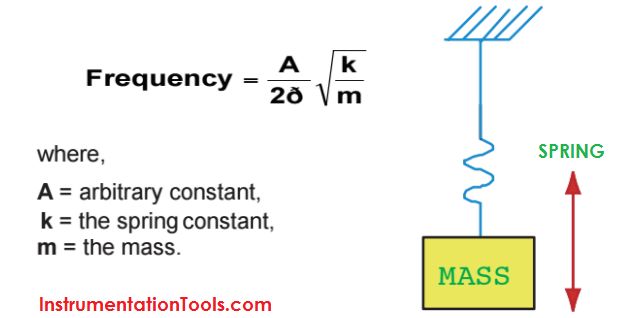
If the spring constant or the mass changes, the frequency of vibration or “natural frequency” will change. This concept can be related to a vibrating tube densitometer. The spring constant (k) can be related to the stiffness of the tubing.
The mass (m) can be related to the mass of the tubing plus the mass of the liquid in the tubing. As the mass (or density) of the fluid in the tubing varies, the natural frequency varies.
Vibrating Tube Densitometers Principle:
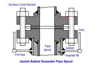
A vibrating tube densitometer is basically a spring-mass system in which the frequency of vibration of the tubing is measured and related to the fluid density. The tube assembly is supported at each end and is mechanically “excited” or displaced using electromechanical devices, so that the assembly will vibrate at the natural frequency.
As previously discussed, the frequency of vibration of the tube assembly will vary as the density of the fluid in the tubing changes. The tube assembly must have appropriate mechanical properties to resist corrosive attack from the fluid, be able to contain the pipeline pressure, and have proper vibration characteristics.
The actual arrangement of the tubes will vary with manufacturer; parallel tubes, U-tube, and in-line tubing are the most common. The tube material is usually Ni-Span C, stainless steel or Hastelloy, although other materials have been used.
An efficient densitometer installation design will ensure that representative liquid pipeline sample is located inside the tube(s) at all times. The following equation is used to relate the frequency fluid density.
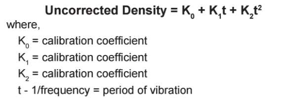
For increased accuracy, compensation for the effects of changing temperature and pressure on the tubing must be performed. To relate to the spring-mass example, changes in temperature and pressure cause small changes to the stiffness of the spring, causing variation in the frequency of vibration.
The frequency shift caused by changing temperature and pressure can be described with second-order equations that are unique for each densitometer.
The coefficients used in these equations are supplied by the manufacturer when the densitometer is purchased or recertified. The coefficients do not change for a specific densitometer.
During field calibration (or proving) of the densitometer, a density correction factor (DCF) is used to adjust the indicated or observed density of the densitometer to the actual density of the liquid. If the density correction factor varies beyond manufacturer recommendations, or the accuracy varies with the fluid density, the densitometer must be examined for possible defects and recertified.
Densitometer Signal Processing
The signal output from a vibrating densitometer is a “square wave” signal with a period or frequency equalling the vibration frequency of the tube assembly. From this signal, the frequency must be measured and the corrections for the effects of fluid temperature and pressure must be applied. The final determination is the density of the fluid.
A flow computer is used to perform these calculations. In many cases, the flow computer is also measuring the pipeline fluid flow rate using a turbine flow meter, an orifice meter, or other flow measurement device.
Using the accumulated data, the fluid mass flow rate can be calculated. Depending on the application, the flow computer output values may be transferred using normal 4-20 mA signals, or conventional digital communication techniques such as RS-232C.
Vibrating Tube Densitometers Animation
Note: The Vibrating Tube Density Meters principle is as same as Coriolis mass flow meter but only application is different. Here we are measuring density as main signal instead of flow.


excellent sir
Gain my experience
Hi, thank you for explaining of density meter calculation, but how I can adjust the K0, K1, K2 constant, let’s say after verification we found that there is a deviation within 5 kg/m3 density. Which constant I have to change and which formula i have to refer. please advise? We use Solartron 7835B model.