Inst ToolsInst ToolsInst Tools
  • Courses
  • Automation
    • PLC
    • Control System
    • Safety System
    • Communication
    • Fire & Gas System
  • Instrumentation
    • Design
    • Pressure
    • Temperature
    • Flow
    • Level
    • Vibration
    • Analyzer
    • Control Valve
    • Switch
    • Calibration
    • Erection & Commissioning
  • Interview
    • Instrumentation
    • Electrical
    • Electronics
    • Practical
  • Q&A
    • Instrumentation
    • Control System
    • Electrical
    • Electronics
    • Analog Electronics
    • Digital Electronics
    • Power Electronics
    • Microprocessor
Search
  • Books
  • Software
  • Projects
  • Process
  • Tools
  • Basics
  • Formula
  • Power Plant
  • Root Cause Analysis
  • Electrical Basics
  • Animation
  • Standards
  • 4-20 mA Course
  • Siemens PLC Course
Reading: Transmitter Calibration Range of a Vessel Level
Share
Notification Show More
Font ResizerAa
Inst ToolsInst Tools
Font ResizerAa
  • Courses
  • Design
  • PLC
  • Interview
  • Control System
Search
  • Courses
  • Automation
    • PLC
    • Control System
    • Safety System
    • Communication
    • Fire & Gas System
  • Instrumentation
    • Design
    • Pressure
    • Temperature
    • Flow
    • Level
    • Vibration
    • Analyzer
    • Control Valve
    • Switch
    • Calibration
    • Erection & Commissioning
  • Interview
    • Instrumentation
    • Electrical
    • Electronics
    • Practical
  • Q&A
    • Instrumentation
    • Control System
    • Electrical
    • Electronics
    • Analog Electronics
    • Digital Electronics
    • Power Electronics
    • Microprocessor
Follow US
All rights reserved. Reproduction in whole or in part without written permission is prohibited.
Inst Tools > Blog > Practical Questions > Transmitter Calibration Range of a Vessel Level

Transmitter Calibration Range of a Vessel Level

Determine the calibration range of a transmitter in order to measure the vessel level into an output signal of 4 to 20 mA.

Last updated: November 12, 2020 9:39 am
Editorial Staff
Practical Questions
No Comments
Share
1 Min Read
SHARE

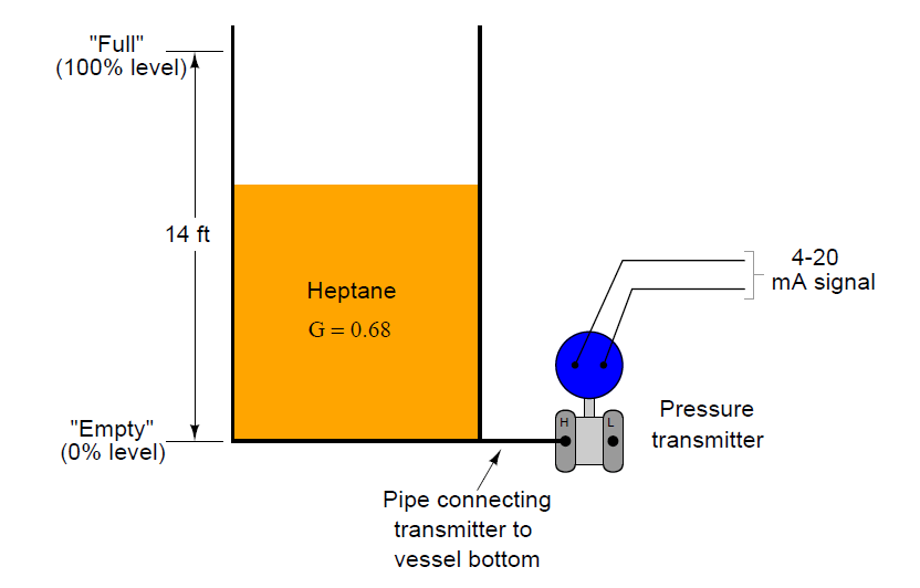
The following storage vessel holds liquid heptane, a hydrocarbon with an approximate specific gravity of 0.68.

A pressure transmitter located at the bottom infers heptane level by hydrostatic pressure (head).

Determine the calibration range of this pressure transmitter in order to properly translate the range of vessel level (0 to 14 feet) into an output signal of 4 to 20 mA.

Transmitter Calibration Range

Transmitter Calibration Range of a Vessel Level Please express the transmitter’s calibration range in units of inches W.C. (inches of water column).

Then, determine the following (assuming the transmitter has been properly calibrated for the application):

Transmitter output signal (mA) at 8 feet of level

Heptane level at 5.7 mA signal output

Answer

Lower range-values (LRV): 0 inches W.C. input = 4 mA output

Upper range-values (URV): 114.24 inches W.C. input = 20 mA output

Transmitter output signal (mA) at 8 feet of level = 13.14 mA

Heptane level at 5.7 mA signal output = 1.4875 feet

Share your answers & explanation with us through the below comments section.

Read Next:

  • Impulse Tubing Leak
  • Control Valve Noise
  • Density and Specific Gravity
  • Pressure Sensing Level Sensor
  • LRV URV of DP Level Transmitter

Credits: Tony R. Kuphaldt

Don't Miss Our Updates
Be the first to get exclusive content straight to your email.
We promise not to spam you. You can unsubscribe at any time.
Invalid email address
You've successfully subscribed !

Continue Reading

Calculate the Thermocouple Output millivolts
Pressure Switch Questions
Calculate the 0%, 50%, and 100% Calibration Points
Tank uses 3 Pressure Transmitters to Measure Level & Density
Troubleshoot Allen Bradley PLC Logic
What Affect the Pressure Measurement Accuracy of a Manometer?
Share This Article
Facebook Whatsapp Whatsapp LinkedIn Copy Link
Share
Leave a Comment

Leave a Reply Cancel reply

Your email address will not be published. Required fields are marked *

Stay Connected

128.3kFollowersLike
69.1kFollowersFollow
210kSubscribersSubscribe
38kFollowersFollow

Categories

Explore More

DP Transmitter Block and Bleed Valves
A Question on Density Gauge
Practical Process Control System Questions & Answers – 11
Programmable Logic Controller (PLC) Questions and Answers – 12
Calculate PSV Lift Pressure
Programmable Logic Controller (PLC) Questions and Answers – 15
Air Pressure Regulator Questions
Overhead Product Pressure Control Loop

Keep Learning

Vehicle Electrical Batteries upgrade

Upgrading the Electrical System in an Automobile

Smart DP transmitter Formula

DP Transmitter Error Calculations

Sump Tank Level Transmitter

Problem with Sump Tank Level Transmitter

PLC program to control pump

Troubleshooting PLC Permissive Inputs

Ladder Diagram circuit

PLC Practice Questions

Problem with Pirani Gauge

Problem with Pirani Gauge

pressure switches relay circuit

Determine the functions of Pressure Switches ?

Manometer Measures Differential Pressure

How Manometer Measures Differential Pressure for Different Fluids?

Learn More

pressurized-water reactor

Runaway Processes

What are Switchgear Interlocks?

What are Switchgear Interlocks?

ControlLogix

Difference Between CompactLogix and ControlLogix

Electrical Machines Questions and Answers

Synchronous Machines Distributed Winding Quiz

Interview Questions on Industrial Wireless

Interview Questions on Industrial Wireless

Troubleshooting a Biased Transistor

Troubleshooting a Biased Transistor

Tubing ACCURATE BENDING

Instrument Tube Fitting Installation – Part 1

Effects of Long Distance Cables on VFD

Effects of Long Distance Cables between VFD and Motor

Menu

  • About
  • Privacy Policy
  • Copyright

Quick Links

  • Learn PLC
  • Helping Hand
  • Part Time Job

YouTube Subscribe

Follow US
All rights reserved. Reproduction in whole or in part without written permission is prohibited.
Welcome Back!

Sign in to your account

Username or Email Address
Password

Lost your password?