Inst ToolsInst ToolsInst Tools
  • Courses
  • Videos
  • Q & A
    • Interview
      • Instrumentation
      • Electronics
      • Electrical
      • Practical Questions
    • MCQ
      • Instrumentation MCQ
      • Electrical MCQ
      • Electronics MCQ
      • Control Systems MCQ
      • Analog Electronics MCQ
      • Digital Electronics MCQ
      • Power Electronics MCQ
      • Microprocessor MCQ
      • Multiple Choice Questions
  • EE
    • Electronics
      • Electronics Q & A
      • Electronic Basics
      • Electronic Devices & Circuits
      • Electronics Animation
      • Digital Electronics
    • Electrical
      • Electrical Basics
      • Electrical Q & A
      • Power Electronics
      • Electrical Machines
      • Electrical Animation
      • Power Systems
      • Switchgear & Protection
      • Transmission & Distribution
  • Measure
    • Control Valves
    • Calibration
    • Temperature
    • Pressure
    • Flow
    • Level
    • Analyzers
    • Switches
    • Vibration
    • Solenoid Valve
  • Control
    • PLC Tutorials
    • Control Systems
    • Safety Instrumented System (SIS)
    • Communication
    • Fire & Gas System
  • More
    • Design
    • Tools
    • Animation
    • Basics
    • Formulas
    • Standards
    • TextBooks
    • Common
    • Software
    • Excel Tools
    • Erection & Commissioning
    • Process Fundamentals
    • Videos
    • Books
Search
All rights reserved. Reproduction in whole or in part without written permission is prohibited.
Reading: Facts on Thermowell Insulation Thickness
Share
Notification Show More
Font ResizerAa
Inst ToolsInst Tools
Font ResizerAa
  • Courses
  • PLC Tutorials
  • Control Systems
Search
  • Courses
  • Videos
  • Q & A
    • Interview
    • MCQ
  • EE
    • Electronics
    • Electrical
  • Measure
    • Control Valves
    • Calibration
    • Temperature
    • Pressure
    • Flow
    • Level
    • Analyzers
    • Switches
    • Vibration
    • Solenoid Valve
  • Control
    • PLC Tutorials
    • Control Systems
    • Safety Instrumented System (SIS)
    • Communication
    • Fire & Gas System
  • More
    • Design
    • Tools
    • Animation
    • Basics
    • Formulas
    • Standards
    • TextBooks
    • Common
    • Software
    • Excel Tools
    • Erection & Commissioning
    • Process Fundamentals
    • Videos
    • Books
Follow US
All rights reserved. Reproduction in whole or in part without written permission is prohibited.
Inst Tools > Blog > Instrumentation Design > Facts on Thermowell Insulation Thickness

Facts on Thermowell Insulation Thickness

Last updated: September 22, 2019 7:56 pm
Editorial Staff
Instrumentation Design Temperature Measurement
2 Comments
Share
3 Min Read
SHARE

Can Insulation Thickness affect Thermowell U-Length ?

Thermowell Tip must be at least 2 mm immersed in Liquid whose temperature is to be measured (As per API 551)

Contents
Can Insulation Thickness affect Thermowell U-Length ?Thermowell Insulation ThicknessGood Engineering practiceNot so good engineering practice !!Clearance (100 mm) = Standout (200 mm) – Insulation Thickness (100 mm)Insulation (On pipe)>>affects>>Standout (Nozzle)>>affects>>U-length (Thermowell)Author : Asad ShaikhArticles You May Like :

In 2-phase service also it is recommended that Tip must be all the way up to Liquid phase for better measurement (PIP Std :-Temperature Measurement criteria)

A Standout of 6” is usually taken as rule of thumb and according the U-length calculated so that Thermowell tip is inserted at least 2 mm in process or more.(depending on client standards)

Now consider The Design Temperature got updated at the latter stages . At this point due to change in Temperature the Insulation thickness increased.

Does this change in insulation affect the Thermowell U-Length?

Yes it does!!

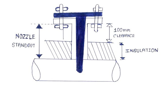
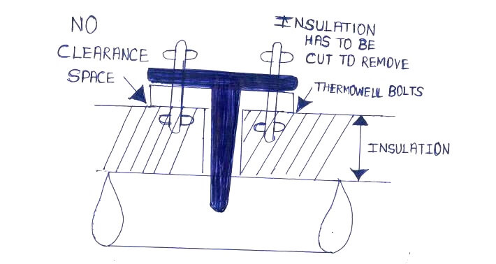
Good Engineering practice is that there has to be clearance of 100 mm (4 inches) between Insulation and the nozzle .This is followed in standard cases because whenever we need to remove the Thermowell and if insulation is all the way up to the nozzle then we will have to cut the insulation to get to the Bolts, Which is not a good practice.

Thermowell Insulation Thickness

Refer the diagram Below .

Good Engineering practice

Thermowell Insulation Thickness

Not so good engineering practice !!

Insulation of Thermowell

Hence for Insulation between 0 to 50 mm we could have Standard standout of 150 mm ( 6 Inch)

But when insulation is 100 mm then standout must increase to 200 mm (8 inches)

Clearance (100 mm) = Standout (200 mm) – Insulation Thickness (100 mm)

Similarly if insulation is 150 mm then standout must increase to 250 mm (10 inches) so on and so forth.

So the Relation is as follows

Insulation (On pipe)>>affects>>Standout (Nozzle)>>affects>>U-length (Thermowell)

Hence we must cross verify at later stages before purchase that will standout affected due to insulation !!

Accordingly ensure whether the thermowell tip actually is in contact with process as per our requirement !!

Thanks for reading !!

Hope this is helpful

PS : As always this is as per best of my current understanding !! I would be very grateful if any updates or corrections are required.

Author : Asad Shaikh

Profile : Linkedin

Articles You May Like :

RTD Troubleshooting Tips

What is Temperature Switch

Temperature Interview Questions

Bi-metal Temperature Sensors

Types of Thermometers

Don't Miss Our Updates
Be the first to get exclusive content straight to your email.
We promise not to spam you. You can unsubscribe at any time.
Invalid email address
You've successfully subscribed !

Continue Reading

How to Select the Right Panel Enclosure for Your Application?
Single Position Calibration of Temperature Bath
Motor Control Signal Interface
Temperature Sensor Failure
When to use a Diaphragm Seal?
Major issues for Sensors Selection
Share This Article
Facebook Whatsapp Whatsapp LinkedIn Copy Link
Share
2 Comments
  • Varneek Mathur says:
    October 29, 2019 at 8:07 pm

    Hi..
    Well written the full article. However i have one observation.
    “Thermowell Tip must be at least 2 mm immersed in Liquid whose temperature is to be measured (As per API 551)”
    But thermowell tip shall be min 2 inches (instead of 2 mm) immersed in the liquid.
    So we can rewrite as:
    “Thermowell Tip must be at least 2 inches immersed in Liquid whose temperature is to be measured (As per API 551)”

    Reply
    • Marcos Escobar says:
      October 11, 2021 at 6:31 pm

      You are correct, it is 2″. Also wondering why the free space from top of insulation to bottom? of the flange is recommended 4″ when I think 2″ will be sufficient (any thoughts?)

      Reply

Leave a Reply Cancel reply

Your email address will not be published. Required fields are marked *

Stay Connected

128.3kFollowersLike
69.1kFollowersFollow
208kSubscribersSubscribe
38kFollowersFollow

Categories

Explore More

Calibration of Temperature Sensor with Indicator
Thermocouple Temperature Measurement Errors
What is Material Take Off (MTO)? – Purpose, Components, Uses
What Temperature are Celsius and Fahrenheit Value Same ?
Magnetic Flow Meters Installation Guidelines
What is a Three-wire RTD ?
Tagging Philosophy for Junction Box, Cable, and Cable Drum
Determine the Status of Lamps and Relays in the Circuit ?
Design and Implement Motor Control – Electrical Engineering
What is Inter Discipline Check (IDC)?

Keep Learning

Van Stone Type Thermowell

Types of Thermowells

Instrument System Architecture and Process Control Design

System Architecture and Process Control Systems Philosophy

Three Wire RTD Temperature Compensation

Ambient Temperature Effects on RTD

Axial Diaphragm Seal Connection

Difference between Axial and Radial Diaphragm Seal Connection?

Selecting Directional Valves

How to Select a Directional Valves

Temperature Transmitter Formula

Calculate Temperature Transmitter Output

Air Consumption Calculation for Control Valves

Air Consumption Calculation for ON/OFF Valves

Effect of Lead Wire Resistance on RTD

Effect of Lead Wire Resistance on RTD

Discover More

What is a Database Server

What is a Database Server? – Types, Comparison

Electrical Traction Multiple Choice Questions and Answers

Electrical Traction Multiple Choice Questions and Answers

PLC Signal Flow

Basic DCS/PLC Signal Flow – Video

Current and Voltage analogy

Current and Voltage Principle Animation

PLC Program for Counting Objects on Conveyor

PLC Program for Counting Moving Objects on Conveyor

Thermowell Problems

Thermowell Problems

progressively sequenced control valves

Progressive Control Valve Sequence

SOA-C02 Exam Certification

Know the Best Path to Achieve SOA-C02 Exam Certification

Follow US
All rights reserved. Reproduction in whole or in part without written permission is prohibited.
Welcome Back!

Sign in to your account

Username or Email Address
Password

Lost your password?