Build the ladder logic program to turn ON and OFF the lamp using push buttons with respect to program logic conditions.
PLC Lamp Control

PLC Problem Logic
Start PB and Stop PB are used to turn ON and OFF the lamp.
It should follow the following two cases.
CASE 1 :
Start PB is used to turn ON the lamp, Same Start PB is thrown again to turn OFF the lamp.
CASE 2 :
Start PB is Pressed to turn on the Lamp, if stop PB is pressed to turn OFF the lamp, Start PB is pressed twice to turn ON the lamp again.

NOTE: Both the cases should satisfy in single program using minimum number of memories. Its user choice to pick the case option.
List of Inputs and Outputs
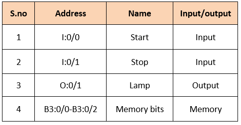
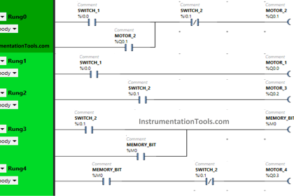
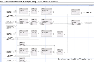
PLC Lamp Program

PLC Lamp Ladder Logic Description
RUNG 0000
Latching rung to operate the system through Master Start and Stop PB.
RUNG 0001
To store the status of start PB (When we released hand after we pressed it for first time) when lamp is in ON condition. Since we are using Push Buttons, Memory Switch B3:0/1 is connected in parallel.
RUNG 0002
To store the status of Start PB ON condition for second time to turn off the lamp (Refer CASE 1 in program logic).
Stop PB is connected in parallel as normally open PB to perform OFF condition of lamp.(Refer CASE 2 in program logic).
Since we are using Push Buttons, Memory Switch B3:0/2 is connected in parallel (Latching).
RUNG 0003
For CASE 2 condition, when lamp is turned off using stop PB, Start PB is pressed twice to turn on Lamp .Counter is used to count the ON condition of start PB.
Rung 0004
Main rung to connect the Previous rung condition in series and parallel to turn ON/OFF lamp according to program logic.
Note: Memory bits are used to store the status and get the sequence of operation.
Conclusion:
The above explained ladder logic for lamp turn ON/OFF is for example only. We can use this example program to understand the working of Push Buttons, memory bit and latching in AB PLC.
Author : Hema Sundaresan
If you liked this article, then please subscribe to our YouTube Channel for PLC and SCADA video tutorials.
You can also follow us on Facebook and Twitter to receive daily updates.
Read Next:
Metro Project using PLC Program


Do you have to reset the counter?
In 4th rung why did you used motor.?