Inst ToolsInst ToolsInst Tools
  • Courses
  • Automation
    • PLC
    • Control System
    • Safety System
    • Communication
    • Fire & Gas System
  • Instrumentation
    • Design
    • Pressure
    • Temperature
    • Flow
    • Level
    • Vibration
    • Analyzer
    • Control Valve
    • Switch
    • Calibration
    • Erection & Commissioning
  • Interview
    • Instrumentation
    • Electrical
    • Electronics
    • Practical
  • Q&A
    • Instrumentation
    • Control System
    • Electrical
    • Electronics
    • Analog Electronics
    • Digital Electronics
    • Power Electronics
    • Microprocessor
Search
  • Books
  • Software
  • Projects
  • Process
  • Tools
  • Basics
  • Formula
  • Power Plant
  • Root Cause Analysis
  • Electrical Basics
  • Animation
  • Standards
  • 4-20 mA Course
  • Siemens PLC Course
Reading: What is PID Controller Bumpless Transfer ?
Share
Notification Show More
Font ResizerAa
Inst ToolsInst Tools
Font ResizerAa
  • Courses
  • Design
  • PLC
  • Interview
  • Control System
Search
  • Courses
  • Automation
    • PLC
    • Control System
    • Safety System
    • Communication
    • Fire & Gas System
  • Instrumentation
    • Design
    • Pressure
    • Temperature
    • Flow
    • Level
    • Vibration
    • Analyzer
    • Control Valve
    • Switch
    • Calibration
    • Erection & Commissioning
  • Interview
    • Instrumentation
    • Electrical
    • Electronics
    • Practical
  • Q&A
    • Instrumentation
    • Control System
    • Electrical
    • Electronics
    • Analog Electronics
    • Digital Electronics
    • Power Electronics
    • Microprocessor
Follow US
All rights reserved. Reproduction in whole or in part without written permission is prohibited.
Inst Tools > Blog > Control Systems > What is PID Controller Bumpless Transfer ?

What is PID Controller Bumpless Transfer ?

Last updated: September 21, 2017 10:39 am
Editorial Staff
Control Systems
1 Comment
Share
4 Min Read
SHARE

Bumpless Transfer

Bumpless transfer is either a manual or automatic transfer procedure used when switching a PID controller from auto to manual or vice versa. Its aim is to keep the controllers output the same when switching auto/manual, that is if the controller is at 50% output in auto it should retain that 50% output as you switch it to manual. If you switch from manual to auto the same should apply. Most modern PID controllers have bumpless transfer built in, including PLC and DCS PID controllers.

The term bumpless transfer refers to the process being controlled, meaning that the process is not disturbed when switching the PID controller from Auto to manual or from manual to auto.

“Bumpless transfer” is a term used to describe the desired action a controller (PID, for example) is expected to maintain when transferring from manual to auto mode, or vice-versa.

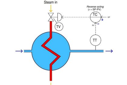
In auto mode, the controller calculates a deviation between the desired setpoint and the actual value of the process variable, and adjusts the signal to the output to reduce the value of the deviation (or error).

However, in manual mode, the operator decides what this output signal will be, bypassing the auto mode settings, and this value could be different than what the controller has calculated.

In this case, when the operator switches from manual to auto,the controller applies its calculated output value to the process, and since there is a good chance the auto and manual outputs do not match, there will be a “bump” in the process: valves will open/close suddenly, pumps will increase/ decrease in speed abruptly… until the controller adapts the output values again. This is bad for the process (sudden jumps in actual value shows lack of overall control) and can affect adversely the process actuators (valves and pumps and motors do not like being forced to change control values quickly; repeated fast changes can even damage the actuators).

To produce a bumpless transfer, the PID controller will force the manual mode output value to the output in auto mode (no bump) and then ramp slowly the auto output to the value calculated by the controller in auto. This way passage from manual to auto is gradual, the process shows no abrupt changes and the process actuators are not affected.

Bumpless Tuning

In this case, without a bumpless tuning feature, the bump occurs due to changing controller gain or derivative settings during controller tuning.

It is because of the bump in controller output caused by changing tuning settings that it is good practice to place a controller in manual mode momentarily while making tuning changes. Because most controllers have bumpless transfer, it eliminates the bump when switching the controller back to auto after making the tuning changes in manual mode.  However, this becomes a problem if the tuning settings are changed, as in the case of gain scheduling.

Bumpless tuning can be achieved without the need to place the controller in manual mode by calculating how much the controller output will jump due to the new proportional and derivative settings, and subtracting an equal quantity from the integral term, so that the sum of the three terms (the controller output) remains unchanged.  Similar to bumpless transfer, bumpless tuning can also be achieved by using a velocity algorithm.

Also Read: Split RangeControl

Don't Miss Our Updates
Be the first to get exclusive content straight to your email.
We promise not to spam you. You can unsubscribe at any time.
Invalid email address
You've successfully subscribed !

Continue Reading

Why 24 Volts DC Power Supply is used? – Industrial Automation Systems
Chemical Reactor Temperature Control System
What is 21 CFR in SCADA and HMI Systems?
How to Design a System Architecture in Industrial Automation?
Problem on Pressure and Level Control Loops
2-wire Transmitters Current Loops
Share This Article
Facebook Whatsapp Whatsapp LinkedIn Copy Link
Share
1 Comment
  • Hoàng says:
    March 20, 2018 at 9:30 am

    dear sir,

    I consider if bumps also happen in case we have PLC package connected to DCS and we selected control mode PLC/DCS mode or not ?

    Thanks sir.

    Reply

Leave a Reply Cancel reply

Your email address will not be published. Required fields are marked *

Stay Connected

128.3kFollowersLike
69.1kFollowersFollow
208kSubscribersSubscribe
38kFollowersFollow

Categories

Explore More

4–20 mA Process Control Loops
Turbine-Compressor System Architecture
PLC Connection between Instrument, Junction Box, Marshalling & System Cabinet
The Idea Behind Shielded Cables
Self-regulating Processes – Liquid Flow Control
14 Basic Control Systems Questions for Interview Preparation
Process Switches and Alarms
4-20 mA Transmitter Wiring Types : 2-Wire, 3-Wire, 4-Wire

Keep Learning

Derivative (Rate) Controller

Derivative (Rate) Control Theory

Control Loop

What is a Control Loop ?

Supervisory Control

Supervisory Control

Electrical Ground Loop

How to Solve Electrical Ground Loop Problems?

Switches, Repeaters, Bridges, Routers, Firewalls

Purpose of Gateways, Bridges & Routers in Networking

Control Valve Split Range Example - 2

Control Valve Split Range Example

Design Process Control & Safety Systems

Design View of Supplying Process Control and Safety Systems

How Twisted Wire Cables Eliminates Noise Voltage

Inductive Coupling Effects

Learn More

Faults in a Transformer

Yokogawa differential pressure transmitter

Basics of Differential Pressure Transmitters

basic-electronics-questions-answers

Basic Electronics Questions & Answers

Pneumatic Amplifying Relay

Determine Effect of Each Fault for Pneumatic Force-balance System

Fire and Gas System Interview Questions & Answers

Fire and Gas System Interview Questions & Answers

Electric Drives and Traction Objective Questions and Answers

Electric Drives and Traction Interview Questions

Frequency Response MCQ

Polar Plots MCQ

Sounding Level Transmitter Working Animation

Follow US
All rights reserved. Reproduction in whole or in part without written permission is prohibited.
Welcome Back!

Sign in to your account

Username or Email Address
Password

Lost your password?