Inst ToolsInst ToolsInst Tools
  • Courses
  • Automation
    • PLC
    • Control System
    • Safety System
    • Communication
    • Fire & Gas System
  • Instrumentation
    • Design
    • Pressure
    • Temperature
    • Flow
    • Level
    • Vibration
    • Analyzer
    • Control Valve
    • Switch
    • Calibration
    • Erection & Commissioning
  • Interview
    • Instrumentation
    • Electrical
    • Electronics
    • Practical
  • Q&A
    • Instrumentation
    • Control System
    • Electrical
    • Electronics
    • Analog Electronics
    • Digital Electronics
    • Power Electronics
    • Microprocessor
Search
  • Books
  • Software
  • Projects
  • Process
  • Tools
  • Basics
  • Formula
  • Power Plant
  • Root Cause Analysis
  • Electrical Basics
  • Animation
  • Standards
  • 4-20 mA Course
  • Siemens PLC Course
Reading: Reading Electrical Schematics
Share
Notification Show More
Font ResizerAa
Inst ToolsInst Tools
Font ResizerAa
  • Courses
  • Design
  • PLC
  • Interview
  • Control System
Search
  • Courses
  • Automation
    • PLC
    • Control System
    • Safety System
    • Communication
    • Fire & Gas System
  • Instrumentation
    • Design
    • Pressure
    • Temperature
    • Flow
    • Level
    • Vibration
    • Analyzer
    • Control Valve
    • Switch
    • Calibration
    • Erection & Commissioning
  • Interview
    • Instrumentation
    • Electrical
    • Electronics
    • Practical
  • Q&A
    • Instrumentation
    • Control System
    • Electrical
    • Electronics
    • Analog Electronics
    • Digital Electronics
    • Power Electronics
    • Microprocessor
Follow US
All rights reserved. Reproduction in whole or in part without written permission is prohibited.
Inst Tools > Blog > Electrical Theory > Reading Electrical Schematics

Reading Electrical Schematics

Last updated: October 6, 2018 7:06 pm
Editorial Staff
Electrical Theory
No Comments
Share
3 Min Read
SHARE

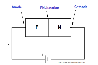
To read electrical system diagrams and schematics properly, the condition or state of each component must first be understood. For electrical schematics that detail individual relays and contacts, the components are always shown in the de-energized condition (also called the shelfstate).

To associate the proper relay with the contact(s) that it operates, each relay is assigned a specific number and/or letter combination. The number/letter code for each relay is carried by all associated contacts. Figure 14 (A) shows a simple schematic containing a coil (M1) and its contact. If space permits, the relationship may be emphasized by drawing a dashed line (symbolizing a mechanical connection) between the relay and its contact(s) or a dashed box around them as shown in Figure 14 (B).

Figure 14 (C) illustrates a switch and a second set of contacts that are operated by the switch.

Reading Electrical Schematics

Reading Electrical Diagrams

Figure 14 Examples of Relays and Relay Contacts

When a switch is used in a circuit, it may contain several sets of contacts or small switches internal to it. The internal switches are shown individually on a schematic.

In many cases, the position of one internal switch will effect the position of another. Such switches are called ganged switches and are symbolized by connecting them with a dashed line as shown in Figure 15 (A).

In that example, closing Switch 1 also closes Switch 2. The dashed line is also used to indicate a mechanical interlock between two circuit components. Figure 15 (B) shows two breakers with an interlock between them.

Gang Switch Principle

Figure 15 Ganged Switch Symbology

In system single line diagrams, transformers are often represented by the symbol for a single- phase air core transformer; however, that does not necessarily mean that the transformer has an air core or that it is single phase. Single line system diagrams are intended to convey only general functional information, similar to the type of information presented on a P&ID for a piping system.

The reader must investigate further if more detail is required. In diagrams depicting three-phase systems, a small symbol may be placed to the side of the transformer primary and secondary to indicate the type of transformer windings that are used.

Figure 16 (A) shows the most commonly used symbols to indicate how the phases are connected in three-phase windings. Figure 16 (B) illustrates examples of how these symbols appear in a three-phase single line diagram.

Three Phase Symbols

Figure 16 Three-Phase Symbols

Don't Miss Our Updates
Be the first to get exclusive content straight to your email.
We promise not to spam you. You can unsubscribe at any time.
Invalid email address
You've successfully subscribed !

Continue Reading

Compound Generators
Capacitor
Power Factor
DC Motor Theory
DC Motor Torque
Shunt-Wound Motor Operation
Share This Article
Facebook Whatsapp Whatsapp LinkedIn Copy Link
Share
Leave a Comment

Leave a Reply Cancel reply

Your email address will not be published. Required fields are marked *

Stay Connected

128.3kFollowersLike
69.1kFollowersFollow
210kSubscribersSubscribe
38kFollowersFollow

Categories

Explore More

DC Machines Terminology
Discharge and Charging of Lead-Acid Battery
Resistance in Parallel Circuits
Electrical Diagrams and Schematics
Series and Parallel Inductors
4-Wire, Three-Phase Wye Wiring System
AC Generator Theory
4-Wire, Three-Phase Delta Wiring System

Keep Learning

DC Circuit Node Equations

DC Circuit Analysis Node Equations

Electrical Symbols

Electrical Symbols

Three Phase To Single Phase Wiring Connections

Single Phase Power Wiring Schemes

circuit breaker principle

What is a circuit breaker ?

Calculate Power in Parallel RL Circuit

Calculate Power in Parallel RL Circuit

Units of Electrical Measurement

Units of Electrical Measurement

Marking Polarity

DC Circuit Analysis Loop Equations

Simple RL Circuit

Impedance in RL Circuits

Learn More

PLC Programming Examples using Timer

Basic PLC Ladder Programming Example

In this article, you will learn the configuration of PlantPAx library in factory talk studio of Rockwell Automation.

Configuration of PlantPAx Library in Factory Talk Studio

Artificial Intelligence Projects

Artificial Intelligence Projects List and Ideas for Students

Industrial Plasma Systems

Why PDMS is Used For Fabrication?

Testing of Pneumatic Systems

Panel and Field Pneumatic Controller’ Bumpless Transfer Issues

BP Refinery Explosion

Learnings from the BP Refinery Explosion at Texas City

Electrical Traction Multiple Choice Questions and Answers

Electrical Traction Multiple Choice Questions and Answers

cross

Tube Fitting Types

Menu

  • About
  • Privacy Policy
  • Copyright

Quick Links

  • Learn PLC
  • Helping Hand
  • Part Time Job

YouTube Subscribe

Follow US
All rights reserved. Reproduction in whole or in part without written permission is prohibited.
Welcome Back!

Sign in to your account

Username or Email Address
Password

Lost your password?